


8
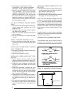
b. F=Flat Flashing; flexes from 0/12 to 1/12 roof
slope.
c. S=Slant Flashing. 2.5/12 Slope flexes from 1/
12 to 4/12 roof slope, 4/12 flexes from 3/12
to 5/12.
d. Stainless steel roof jacks are available.
e. If the roof jack crown is covered or blocked
with snow, the furnace will not operate prop-
erly. If the home is located in regions where
snow accumulation exceeds 7” (HUD
snowload zones) use an external roof jack
extension p/n 901937.
f. M1 furnaces may be used with roof jacks as
tall as 170” (except M1M 056 & M1B 066
models, which are limited to 120”). An internal
roof jack extension (p/n 901935 - 10”, p/n
903107 - 18”) can be used to increase roof
jack height. All connections inside the home
must be made below the ceiling.
These extensions are available as optional
accessories and may be purchased through
your NORDYNE distributor.
h. Gas piping is not run in or through the return
duct system.
i. Test the negative pressure in the closet with
the air-circulating fan operating at high speed
and the closet closed. The negative
pressure is to be no more negative than
minus 0.05 inch water column.
j. Air conditioning systems may require more
duct register and open louver area to ob-
tain necessary airflow. Use NORDYNE’s
certiduct program to determine proper duct
size for A/C.
8.AIR DISTRIBUTION SYSTEMS
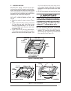
For proper air distribution, the supply duct
system must be designed so that the static
pressure measured external to the furnace
does not exceed the listed static pressure
rating shown on the furnace rating plate.
Location, size, and number of registers should
be selected on the basis of best air distribution
and floor plan of the home.
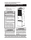
!
CAUTION:
HAZARD OF ASPHYXIATION: Do not
cover or restrict return air opening.
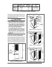
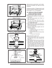
9.ROOF JACK SELECTION
Note: Install only Roof Jack Assemblies listed
in Table 5 on this heating appliance.
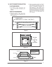
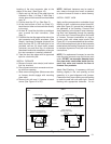
a. Determine depth of ceiling cavity from center
of roof opening to center of ceiling opening.
(See Dimension “A” in Figure 6.)
b. Determine ceiling height and subtract height
of furnace. (See Dimension “B” in Figure 6.)
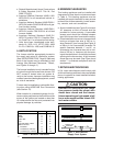
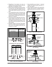
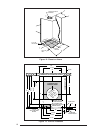
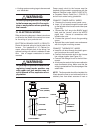
c. Add dimensions A + B (and X from Table 6 and
Figure 7 if slant deck flashing is used). The
total length of (A + B + X) must be within the
minimum and maximum range of one of the
Roof Jacks listed in Table 5.
APPLICATION NOTES:
a. FAW, FAWT, SAW and SAWT Series Roof
Jacks with a 5" diameter inner vent pipe may
be used with all models of M1 Series gas and
oil furnaces.
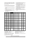
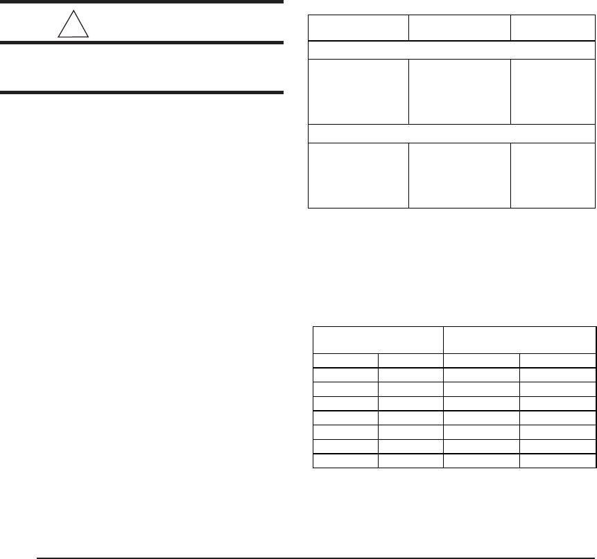
Table 6. Slant Deck Flashings
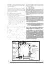
Table 7. Floor Cavity Sizes
Optional Deck Flashings for Flat and 2.5/12 Pitch
Roof Jacks.
(4/12 Pitch Roof Jacks not applicable.)
USE SLANT DECK
IF ROOF PITCH IS: FLASHING NO. "X" FACTOR IS:
"F Series Roof Jack
2" in 12" 903893 (2.5/12) 2-1/8"
2-1/2" in 12" 903893 (2.5/12) 2-1/2"
3" in 12" 903894 (3/12) 2-7/8"
3-1/2" in 12" 903894 (3/12) 3-1/4"
4" in 12" 903895 (4/12) 3-5/8"
"S" Series Roof Jack (2.5/12 Pitch only)
4-1/2" in 12" 903895 (2.5/12) 2-1/8"
5" in 12" 903895 (2.5/12) 2-1/2"
5-1/2" in 12" 903894 (3/12) 2-7/8"
6" in 12" 903894 (3/12) 3-1/4"
6-1/2" in 12" 903895 (4/12) 3-5/8"
English Metric (mm)
Finger Tab Screw Down
7/8" 22 901987 904008
2" 51 901988 904009
4-1/4" 108 901989 904010
6-1/4" 159 901990 904011
8-1/4" 210 901991 904012
10-1/4" 260 901992 904013
12-1/4" 311 901993 904014
Use Duct Connector
Model Part Number:
If "X"
(
Floor Cavit
y)
is: