


15
c. Venting system warning tags to be removed
and discarded.
!
WARNING:
Failure to properly secure the flue pipe
to the furnace may result in fire, explo-
sion or asphyxiation when operating
the furnace.
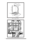
13. ELECTRICAL WIRING
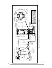
Refer to the wiring diagram in these instructions
or affixed to the inside of the control box cover
for the wiring of your particular unit.
ELECTRICAL BRANCH SUPPLY CIRCUITS.
Route all electrical wiring to the left side of the
furnace. For installation of “A” Cabinet fur-
naces, allow sufficient slack in the wiring if an
optional cooling coil cabinet is added at a later
time.
Use of copper conductors is recom-
mended.
!
WARNING:
Any attempt to operate furnace before
replacing transit-mode weather cap
with upper roof jack section may re-
sult in hazard of fire, explosion or as-
phyxiation.
Power supply circuit to the furnace must be
installed and grounded in accordance with the
National Electrical code (ANSI-C1/NFPA-70),
or Canadian Electric Code Part 1 (CSA 22-1)
and all local codes having jurisdiction.
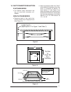
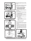
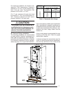
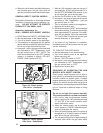
CONNECT POWER SUPPLY WIRES
a. Remove the furnace control panel cover.
b. Insert 115 volt wires through the strain relief
on the left side of the furnace control box (see
Figure 25).
c. Connect the “hot” wire to the BLACK pigtail
lead, and the “neutral” wire to the WHITE
pigtail lead. Secure all connections with
suitable wire nuts.
d. Connect the “ground” wire to the grounding
screw.
e. Reinstall the control panel cover and secure
with the original mounting screws.
CONNECT THERMOSTAT WIRES
a. Insert 24 volt wires through the plastic grom-
met just above the control panel.
b. Connect the thermostat wires to the furnace
low voltage pigtails (see Figure 25).
c. Connect low-voltage circuit to the wall ther-
mostat.
d. A hole may be made in the furnace cabinet to
ease thermostat wiring. Make sure that the
wiring is protected from the sharp edge of the
added hole.
NOTE: The thermostat should be installed 4 to
5 feet above the floor on an inside wall which is
relatively free from direct sources of heat or
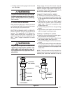
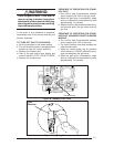
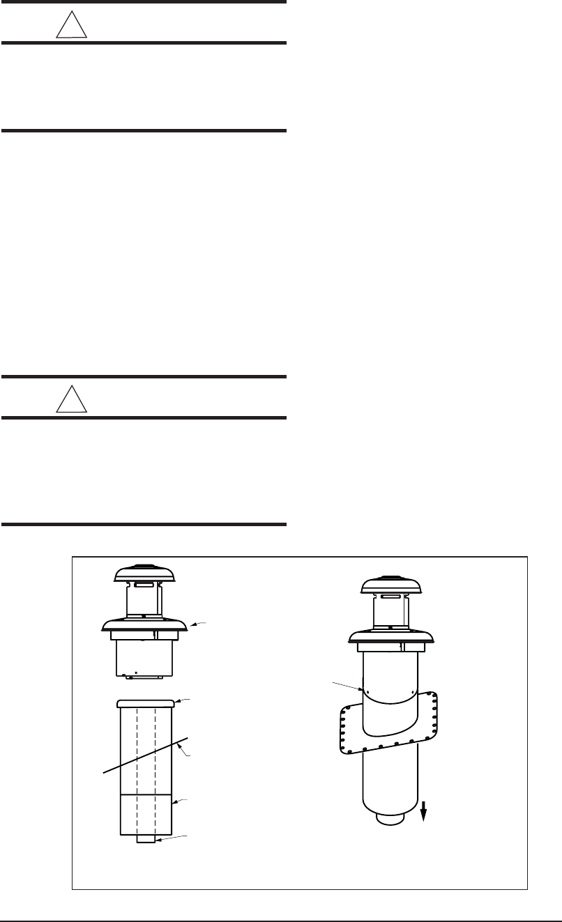
SCREWS
COMPLETED
ASSEMBLY
TO FURNACE
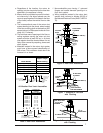
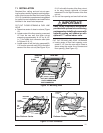
UPPER ROOF
JACK (CROWN)
INNER FLUE
PIPE
FLUE ASSEMBLY
OUTER PIPE
FLASHING
WEATHER CAP
Figure 24.