


6
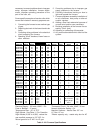
ALL MODELS CLOSET ALCOVE
Front 6" 18"
Back 0" 0"
Sides 0" 0"
Roof Jack 0" 0"
Top 6" 6"
Top and Sides of Duct 0" 0"
Bottom of Duct
B Cabinet 0" 0"
A Cabinet (w/ coil box) 0" 0"
A Cabinet (w/o coil box) 1/4" 1/4"
Table 4. Minimum Clearances
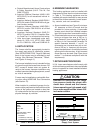
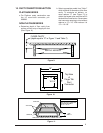
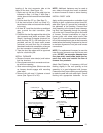
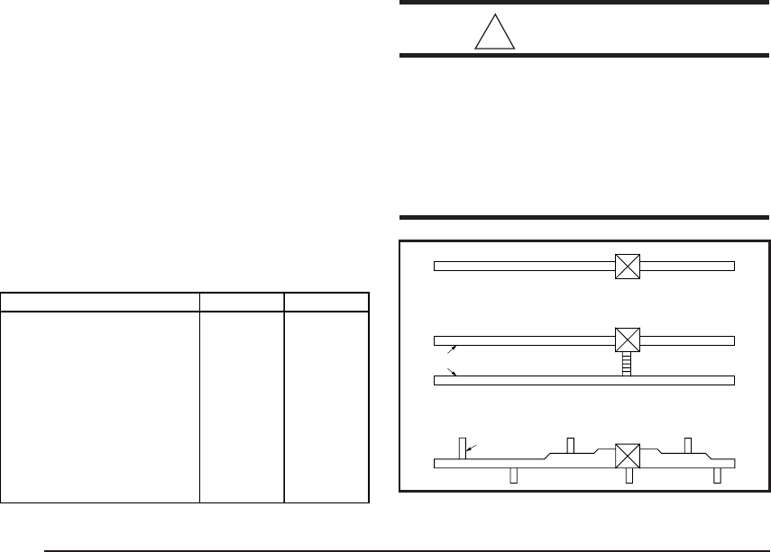
Figure 5. Non-Platinum
Supply Duct System
A Single trunk duct
B
Dual trunk duct
w/crossover connector
C
Transition duct
w/branches
a. Federal Manufactured Home Constructions
& Safety Standard (H.U.D. Title 24, Part
3280.707[a][2])
b. American National Standard (ANSI-119.2/
NFPA-501C) for all recreational vehicle in-
stallations.
c. American National Standard (ANSI-Z223.1/
NFPA-54) and/or CAN/CGA B149 for all gas-
fired furnace models.
d. American National Standard (ANSI-Z95.1/
NFPA-31) and/or CSA B139 for all oil-fired
furnace models.
e. American National Standard (ANSI-C1/
NFPA-70) and/or CSA 22.1 Canadian Elec-
tric Code Part 1 for all electrical field wiring.
f. Units have been investigated under stan-
dards UL 307A & B, UL727-1999, ANSI
21.47a - CAN/2.3a - 1995, and CSA B140.10.
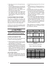
5.UNIT LOCATION
The furnace shall be appropriately located to
the supply and return air distribution system.
(See “AIR DISTRIBUTION”, Page 8) Sides and
back of the furnace may be enclosed by wall
framing. (See “Minimum Clearances,” Table 4,
and Figures 2 through 5.)
The furnace installation is only intended for free
air return through the furnace door louvers. DO
NOT connect a ducted return air system di-
rectly to the furnace. Improper installation may
create a hazard and damage equipment, as well
as void all warranties.
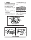
Furnace may be installed on combustible floor-
ing when using NORDYNE Duct Connectors
(see Section 10).
When installed in a residential garage, the fur-
nace must be positioned so the burners and the
source of the ignition are located no less than
18 inches above the floor and protected from
physical damage by vehicles.
6.MINIMUM CLEARANCES
This heating appliance must be installed with
clearances not less than the minimums shown
in Table 4. This heating appliance must be
installed with ample clearance for easy access
to the air filter, blower assembly, burner assem-
bly, controls, and vent connections.
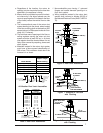
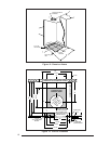
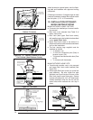
a. Alcove installations (see Figure 2): minimum
18" clearance at front of furnace shall be
provided for future servicing. A removable
access panel should be installed between
top of the furnace door frame and the ceiling.
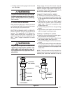
b. Closet installations must use a louvered door
having a minimum free area of 235 sq. in.
when located 6" from furnace (See Figure 3)
or 390 sq. in. for 5 ton ready M1 furnaces. For
special clearance between 1" and 6", re-
quirements are a louvered door with a mini-
mum of 250 sq. in. free area, with the open-
ings in the closet door in line with the louvered
openings in the furnace door . A fully louvered
closet door may be used (See Figure 4 and
section 7.i. to evaluate compliance with this
requirement).
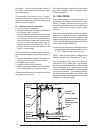
7.RETURN AIR PROVISIONS
U.S.A. home manufacturers shall comply with
all of the following conditions to have acceptable
return air systems for closet installed forced air
heating appliances:
!
CAUTION:
HAZARD OF ASPHYXIATION: Nega-
tive pressure inside the closet, with
closet door closed and the furnace
blower operating on high speed, shall
be no more negative than minus 0.05
inch water column.