


5
Carefully review these responsibilities with your
manufactured housing dealer, service com-
pany or gas supplier so there will be no misun-
derstanding at a later time.
!
CAUTION:
• Never attempt to alter or modify this
furnace or any of its components.
• Never attempt to repair damaged or
inoperable components. Such action
could cause unsafe operation, explo-
sion, fire and/or asphyxiation.
• If a malfunction has occurred, or if
you feel that the furnace is not oper-
ating as it should, contact a qualified
service agency or gas utility for as-
sistance.
4.INSTALLATION STANDARDS
Installer shall be familiar with and comply with all
codes and regulations applicable to the instal-
lation of these heating appliances and related
equipment. In lieu of local codes, the installation
shall be in accordance with the current provi-
sions of one or more of the following standards.
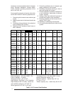
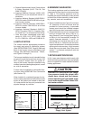
Table 3. Field Installation Blower Assemblies
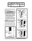
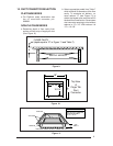
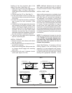
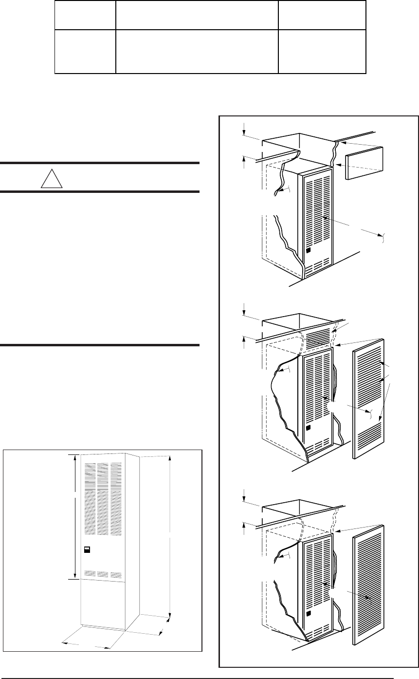
Figure 1. Overall Dimensions
“A”- 56"
23 3/4"
“B”- 76"
19 3/4"
“A” Model-
w/o Coil Cabinet
“B” Model-
w/Coil Cabinet
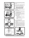
Removable access
panel should be
installed above
furnace door frame
to access roof jack
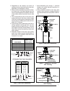
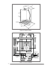
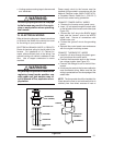
Nearest
Wall or
Partition
18"
(457 mm)
6" (152 mm)
Top Clearance
0" Side
Clearance
to Furnace
Cabinet
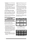
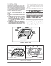
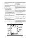
6" (152 mm)
Top Clearance
0" Side
Clearance
to Furnace
Cabinet
Provide min. 235
sq. in. (1516 cm )
open free area in
front or side wall
2
or
In closet
door
located
at top,
center
or bottom
CLOSET DOOR
6" (152 mm)
Top Clearance
Provide min. 250
sq. in. (1613 cm )
open free area in
front or side wall
2
a fully
louvered
door may
be used
CLOSET DOOR
6"
(152 mm)
1"
(25 mm)
0" Side
Clearance
to Furnace
Cabinet
or
in closet
door
Figure 4. Special 1” Clearance
Figure 3. Closet Installation
Figure 2. Alcove Installation
A/C Capacity
Blower Wheel Motor-Hp Ton
903773 10 x 8 1/4 2, 2½ & 3
903413 11 x 8 1/2 2, 2½, 3 & 4
903414 11 x 8 3/4 2, 2½, 3, 4 & 5
Part No.
Blower / Motor Assembly