


27
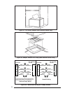
d. To remove the gas valve assembly, remove
screw(s) from gas valve bracket. Gas valve
and spud may be removed. Orifice is located
at the end of the spud (M1G*,M1M*),or re-
move three (3) bolts from U-shaped manifold
plate and orifice assembly (M1B*).
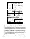
e. Replace the main orifice with the L.P. gas
orifice supplied in the envelope located by the
gas valve. Check to insure the orifice size
matches the nameplate.
f. It is not necessary to convert the pilot orifice.
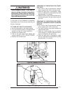
g. For Honeywell gas valves with the regulator
converter (Figure 33), check for the letters
NAT or LP on the pressure regulator cap.
Unscrew the cap, invert it, replace, and
tighten until snug.
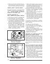
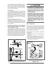
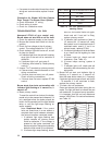
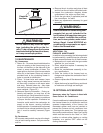
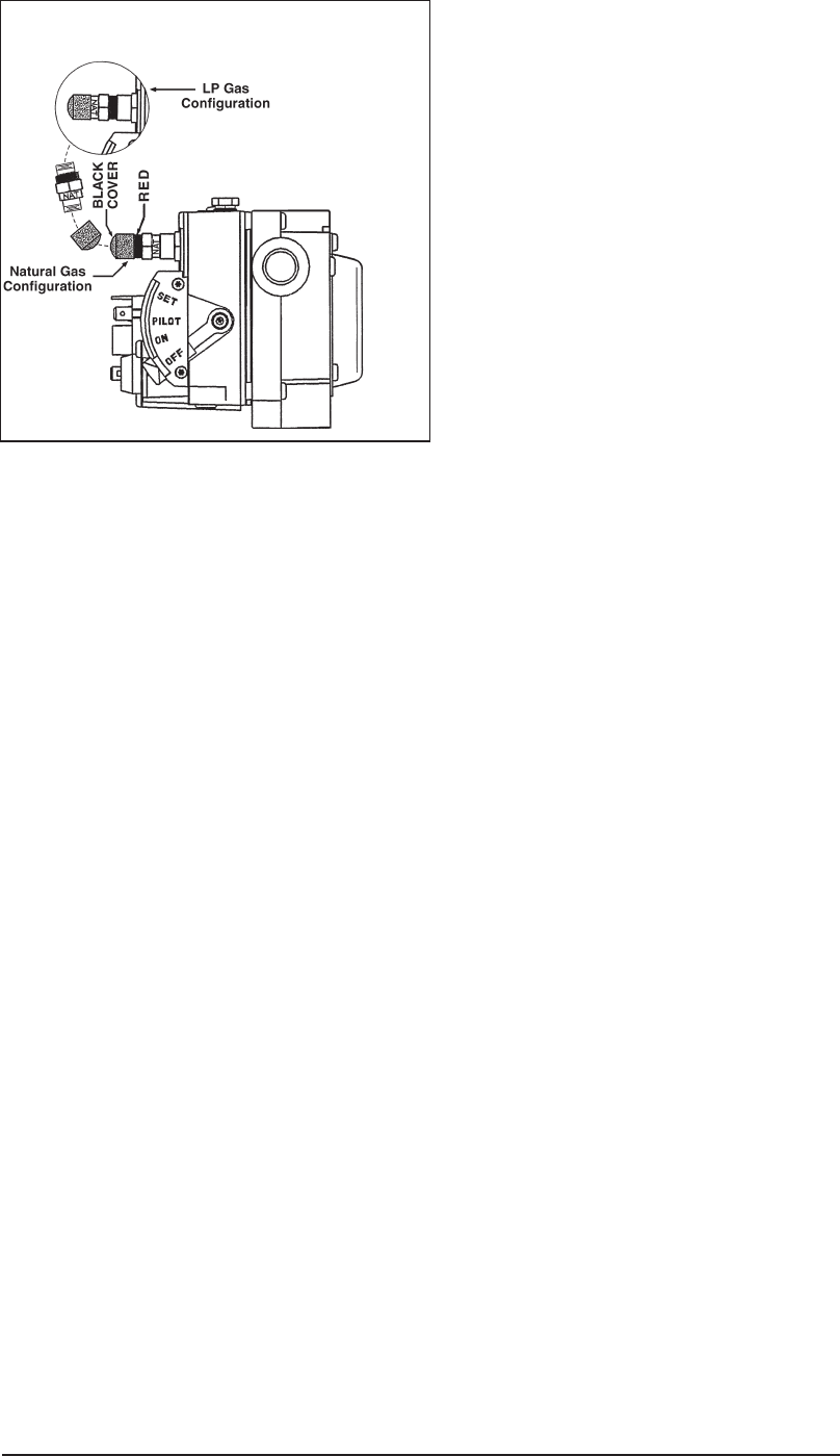
h. For the Robertshaw gas valve with the regu-
lator converter (Figure 34), remove the black
cover and unscrew the converter located on
top of the gas valve. Invert the converter.
(For “LP” the red ring will be located at the
bottom and the “LP” stamping on the con-
verter will appear right side up.) Then screw
converter back into the regulator, hand tight
plus 1/8 turn, and replace the black cover
onto the converter top to protect the threads.
i. Reassemble the burner assembly into the
furnace.
j. Reconnect the gas piping and electrical wires
to the gas valve.
k. Open the manual shut-off valve and follow
the FURNACE START-UP procedure as
outlined previously in this manual to put the
furnace into operation.
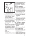
NOTE: The pilot flame is adjustable by turning
the adjustment screw located on the gas valve
with a small screwdriver. (See Figure 29)
TROUBLESHOOTING - STANDING PILOT
MODELS
Main Burner Does Not Come On
a. Check the electrical supply to the furnace.
b. Be sure the furnace On-Off switch is in the
“ON” position.
c. Check for proper thermostat operation.
d. Check for broken or open thermostat wires.
e. Check to make sure the insulation located on
the inside of the front panel is glued securely
around the fan switch and the limit switch.
f. Shut off the electrical supply to the furnace
and remove the electrical box cover.
g. Check for a defective transformer or blown
fuse.
h. Check electrical circuit for proper grounding,
polarity, and make sure the electrical con-
nections are tight.
i. Check to see if limit switches may have failed
to close.
j. Replace the electrical box cover and restore
electrical power to the furnace. Turn the On-
Off switch to “ON” and raise the thermostat
setting above room temperature.
k. Check for 24 volts at the gas valve.
l. Replace the gas valve if the pilot is estab-
lished and it does not open when powered
with 24 volts.
Gas Valve Powered (24 volts)– No Main
Flame
a. The manual shut-off valve must be on.
b. The pilot flame must be established.
c. The gas valve control lever must be in the
“ON” position.
d. Check gas pressure coming to the gas
valve.
e. Replace the gas valve if the main burner does
not come on under the above conditions.
Pilot Will Not Light or Goes Out
a. Check the incoming gas pressure.
b. Check for the proper pilot orifice. See the
nameplate SPECIFICATION.
c. Check for proper pilot flame adjustment. See
“BURNER ADJUSTMENTS.”
d. Check the thermocouple millivoltage.
• Millivoltage should read between 18 and 30
mv.
• If the closed millivolt reading is not between
18 and 30 mv., the gas valve electromagnet
Figure 34. Convertible Pressure
Regulator
Robertshaw
Valve