


26
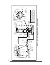
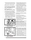
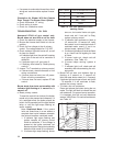
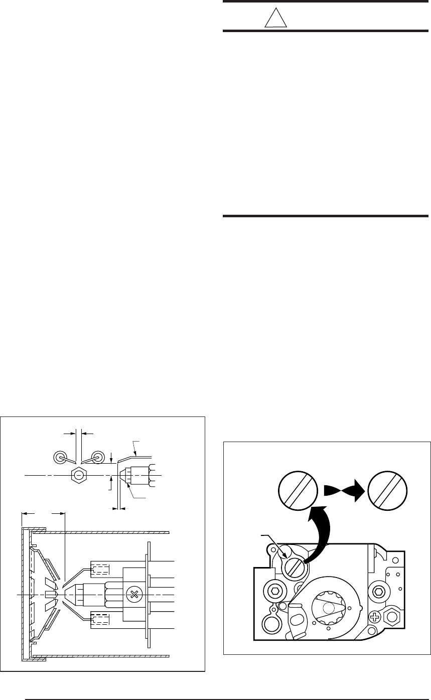
5/32” GAP
ELECTRODE
NOZZLE
0-1/16”
5/16” ABOVE CL
air, to a larger number (clockwise) for more air.
Tighten the lock nut after completing the adjust-
ment. For best results, use instruments to
measure between 8-9% CO
2
after the combus-
tion air has been adjusted.
Oil Gun Only
It is recommended that the CO
2
and Smoke
levels should be measured for maximum per-
formance. CO
2
readings should be 10-11% for
66,000 BTUH furnaces and 12-13% for 86,000
BTUH furnaces. The Smoke should be N0. 0 on
the Bacharach Scale, and 0 to 0.02 negative
draft over fire.
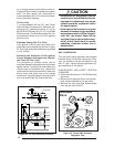
Electrode Setting (Oil Gun Only)
Poor ignition of the oil spray may result if the
electrodes are not adjusted as shown in Figure
32. Do not permit any electrodes to be grounded
to any surface.
Switching the Honeywell R7184 Ignition
Control between Interrupted and Intermit-
tent Duty (Oil Gun Only)
The Honeywell oil primary control can be
switched between interrupted and intermittent
ignition control. To switch from interrupted duty
(Factory set) to intermittent duty, remove the
igniter wire from the blue control wire. Attach the
burner motor and igniter wire to the orange
control wire. Cap and reseal the orange control
wire. Cap and isolate the blue control wire.
!
CAUTION:
• Combustion air adjustment must be
made only by a qualified technician.
Improper air adjustment may cause
unsafe operation, explosion and/or
fire asphyxiation.
• If the input to the furnace is too great
because of excessive gas pressure,
wrong size nozzle or orifice, high alti-
tude, etc., the burner flame will be
sooty and can produce carbon mon-
oxide, which could result in unsafe
operation, explosion and/or fire or
asphyxiation.
GAS CONVERSION
This gas fired heating appliance was shipped
from the factory for use with natural gas. How-
ever, the appliance can be converted for use
with LP gas. Use the following procedure for
gas conversion of the burner.
ATMOSPHERIC AND DIRECT IGNITION
FURNACES
a. Follow the instructions to “Turn Off Gas to the
Appliance.”
b. Disconnect the gas pipe union and the elec-
trical wires connected to the gas valve.
c. Remove the pilot tube and thermocouple
from the gas valve (M1G*).
1 3/8”
Figure 32. Oil Gun electrode Position
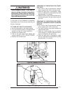
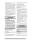
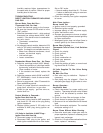
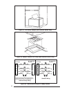
Figure 33. Convertible Pressure
Regulator Cap
PRESSURE
REGULATOR
CAP
M11678
N
A
T
N
A
T
L
P
L
P
N
A
T
N
A
T
OR
OTHER SIDE
OF CAP
Honeywell
Valve