


16
If the heat anticipator is set too low, the furnace
may cycle frequently and not provide comfort
to the homeowner.
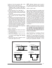
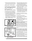
14. FUEL PIPING
Sizing and installation of fuel lines must be in
accordance with federal, state and local regu-
lations. All piping shall be black iron pipe, or
equivalently sized steel tubing. Internally tinned
copper tubing may be used for gas supply
systems.
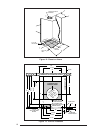
Fuel line installations other than typical installa-
tions shown in Figures 26 and 27 must comply
with the fuel piping provisions stated in the
Federal Manufactured Home Standard (H.U.D.
TITLE 24, PART 280) and the National Fuel Gas
Code (ANSI-Z223.1/NFPA-54).
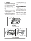
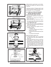
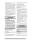
a. Optional fuel inlet lines are available for all gas
furnace models to permit the addition of a 1/
2" F.P.T. shut-off valve above the floor.
NOTE: Shut-off valve must be designed and
listed for use with liquid petroleum (L.P. gas).
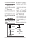
The gas supply to your home will either be
Natural Gas or L.P. (bottle gas). Your furnace
is factory equipped to operate on Natural Gas.
If your gas supply is L.P. (bottle gas), you must
contact a qualified serviceman or gas supplier
to convert the furnace. The necessary instruc-
tions for the gas conversion are found on the
lighting instruction label attached to the furnace
in Section 16, Service Guide.
cold drafts. The nominal anticipator setting is
0.4. (Refer to the thermostat literature for addi-
tional information.)
Five-conductor thermostat wire is recom-
mended for 24 volt low-voltage circuit (2-wire is
required for furnace only; 5-wire for heating and
optional cooling systems).
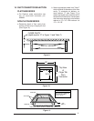
For Platinum-ready Construction:
a. Use a heat/cool thermostat.
b. Run thermostat wire from the Thermostat to
the Furnace (see Figure 39).
c. Using thermostat wire with at least two wires
(four wire is recommended), run thermostat
wire from the Furnace to the intended loca-
tion of the Platinum-series unit. Leave at least
six feet of extra thermostat wire at the in-
tended location for future hook-up. Coil re-
maining six feet of wire and attach to the
home’s undercarriage.
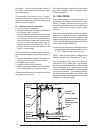
Once the furnace is installed check the thermo-
stat anticipator against the nominal setting of
0.4:
1. Connect the milliamp meter in series with one
of the gas valve’s low voltage terminals.
2. Energize the gas valve.
3. Read the value of the milliamps.
4. Adjust the heat anticipator of the thermostat
to the value read on the milliamp meter.
If the heat anticipator is set too high, the furnace
may delay in coming on.
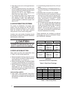
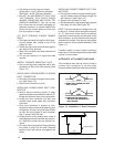
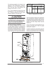
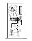
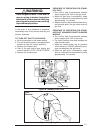
Figure 25. Control Panel (All Models)
To Combustion
Blower or
Flame Roll-Out
Switch
Thermostat Wires
Blower
Plug
On-Off
Switch
On-Auto
Switch
(Heating
Models Only)
To Gas Valve
or Burner
Power
Entry
Furnace
Control Box