


17
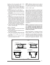
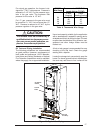
Table 8. Thermostat Wire Gauge
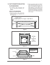
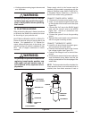
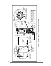
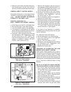
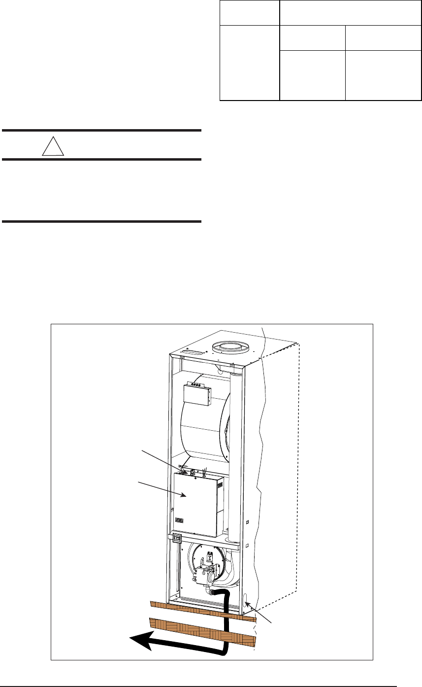
To Gas
Supply
Floor
Control
Panel
On-Off-Fan
Switch
Alt. Fuel
Line Entry
Floor Cavity
Figure 26. Typical Gas Piping
For natural gas operation, the furnace is de-
signed for 7" W.C. inlet pressure. Pressure is
reduced to 3-1/2" W.C. by the pressure regu-
lator in the gas valve. The maximum inlet
pressure for the valve is 13” W.C.
For L.P. gas, pressure to the gas valve must
be more than 11" W.C. but not more than 13"
W.C. Pressure is reduced to 10" W.C. by the
pressure regulator in the gas valve.
!
CAUTION:
The furnace must be converted by a
qualified technician. Improper conver-
sion can cause unsafe operation, ex-
plosion, fire and/or asphyxiation.
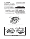
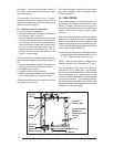
Oil Tank and Piping Installation
The following procedures are recommended
as good practice. However, requirements of
local codes and ordinances, H.U.D. Manufac-
tured Home and Safety Standards or National
Fire Protection Association must be satisfied,
where they apply, for an approved installation.
Use a tank capacity suitable for the application
with a weatherproof, capped fill opening and a
shielded vent to let in air as fuel is used. The tank
must be clean inside before filling. All water, rust,
sediment and other foreign matter must be
flushed out.
A fuel or tank gauge is recommended for easy
checking of the fuel level. Check the gauge
reading with a dipstick.
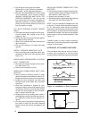
Locate the storage tank conveniently near the
home. For above ground fuel tank installations,
the tank may rest three to four inches off the
T’STAT
Wire Gauge
2-Wire 5-Wire
(Heating) (Heating/Cooling)
24 55 25
22 90 45
20 140 70
18 225 110
Recommended T’STAT Wire
Len
g
th
(
Unit to T’STAT
)