


4
necessary to correct problems due to improper
setup, improper installation, furnace adjust-
ments, improper operating procedure on the
part of the user, etc.
Some specific examples of service calls which
cannot be included in warranty payments are:
1. Converting the furnace to use another type
of gas.
2. Repairing duct work in the home found to be
faulty.
3. Correcting wiring problems in the electrical
circuit supplying the furnace.
4. Resetting circuit breakers, blown fuses or
other switches.
5. Correcting problems due to improper gas
supply pressure to the furnace.
6. Providing instructional training on how to
light and operate the furnace.
7. Furnace problems caused by installation of
an air conditioner, heat pump or other air
comfort devices.
8. Adding a Roof Jack extension because of
unusual wind and/or snow conditions.
9. Revising installation of the furnace flue as-
sembly (Roof Jack).
10. Adjusting or calibrating of thermostat.
11. Any construction debris which falls into flue
system.
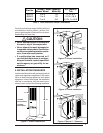
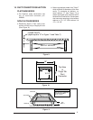
Electrical Supply - 120 volts, 60HZ, 1 Ph.
Fuse or Breaker - 15 amps
Temperature Rise - 45° to 75°F
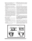
High Altitude - See Table 11. For Canadian
High Altitude (2,000’ to 4,500’), reduce the
gas manifold pressure to 3.0” W.C. for
natural gas and to 8” W.C. for LP gas.
Thermostat Circuit - 24 volts, 60HZ, 30 vac
Normal Anticipator Setting - 0.4
Manifold Pressure - Natural Gas: 3.5” w.c.
LP Gas: 10” w.c.
*Blower capacity only - needs relay box for AC
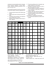
Table 2. M1 Furnace Specifications
Furnace Input Output Orifice No E.S.P. Pilot Ignitor Comb. Motor A/C Ready
Model No MBtu/h MBtu/h Nat. LP In WC Burner Direct Blower Hp Tons
M1GH 056 56 45 29 45 0.3 x 1/8 2*
M1GB 056 56 45 29 45 0.3 x 1/4 3
M1GC 056 56 45 29 45 0.3 x 1/2 4
M1GD 056 56 45 29 45 0.3 x 3/4 5
M1GH 070 70 57 24 42 0.3 x 1/5 2½*
M1GB 070 70 57 24 42 0.3 x 1/4 3
M1GC 070 70 57 24 42 0.3 x 1/2 4
M1GD 070 70 57 24 42 0.3 x 3/4 5
M1GH 077 77 62 21 40 0.3 x x 1/4 3*
M1GB 077 77 62 21 40 0.3 x x 1/4 3
M1GC 077 77 62 21 40 0.3 x x 1/2 4
M1GD 077 77 62 21 40 0.3 x x 3/4 5
M1GH 090 90 72 17 36 0.3 x x 1/4 3*
M1GB 090 90 72 17 36 0.3 x x 1/4 3
M1GC 090 90 72 17 36 0.3 x x 1/2 4
M1GD 090 90 72 17 36 0.3 x x 3/4 5
M1MA 056 56 46 29 45 0.3 x x 1/8 2
M1MB 056 56 46 29 45 0.3 x x 1/4 3
M1MC 056 56 46 29 45 0.3 x x 1/2 4
M1MD 056 56 46 29 45 0.3 x x 3/4 5
M1MA 070 70 57 24 42 0.3 x x 1/5 2½
M1MB 070 70 57 24 42 0.3 x x 1/4 3
M1MC 070 70 57 24 42 0.3 x x 1/2 4
M1MD 070 70 57 24 42 0.3 x x 3/4 5
M1MB 077 77 62 21 40 0.3 x x 1/4 3
M1MC 077 77 62 21 40 0.3 x x 1/2 4
M1MD 077 77 62 21 40 0.3 x x 3/4 5
M1MB 090 90 72 17 36 0.3 x x 1/4 3
M1MC 090 90 72 17 36 0.3 x x 1/2 4
M1MD 090 90 72 17 36 0.3 x x 3/4 5
M1BA 066 66 53 26 43 0.3 x x 1/5 2½
M1BB 066 66 53 26 43 0.3 x x 1/4 3
M1BC 066 66 53 26 43 0.3 x x 1/2 4
M1BB 086 86 68 18 37 0.3 x x 1/4 3
M1BC 086 86 68 18 37 0.3 x x 1/2 4
M1SA 066 66 54
.50 Gph
0.3 x 1/5 2½
M1SB 066 66 54
.50 Gph
0.3 x 1/4 3
M1SC 066 66 54
.50 Gph
0.3 x 1/2 4
M1SB 086 86 71
.65 Gph
0.3 x 1/4 3
M1SC 086 86 71
.65 Gph
0.3 x 1/2 4
Burner Model
AF-10 Nozzle
Spray Angle
80° A