


29
humidity requires higher temperatures for
the same level of comfort. Check for proper
humidity level in the home.
TROUBLESHOOTING -
DIRECT IGNITION FURNACES INCLUDING
GAS GUN
Burner Motor Does Not Run—
Thermostat Calls For Heat
a. Check the electrical supply to the furnace.
b. Be sure the furnace On-Off switch is in the
“ON” position.
c. Defective thermostat circuit - white and red
thermostat low voltage leads (M1M*, M1B*
models). If the burner motor or combustion
fan runs, check:
• Thermostat connections
• Thermostat
d. No voltage to control module - determine if 24
volts (or 120 volts) is available to the control
module. If voltage is not available check for:
• Blown fuse, defective transformer, circuit
breaker, no electrical supply.
• Limit switch open.
• Loose connections.
Combustion Blower Does Run - No Flame
a. Defective centrifugal switch (M1B* Model).
• Check the operation of centrifugal switch
by removing end bell of the burner motor.
• Clean contacts of motor.
• If the contacts are closed, replace the
motor.
b. Defective pressure switch (M1M* and M1G*
077, 090 Models) - check air tube and elec-
trical connections.
c. Burner in purge mode - allow 75 seconds for
flame establishing period.
d. Check for proper electrical connections at
purge timer, control box, or gas valve.
e. Check for gas supply - gas line valve on,
control lever on.
Control Module Is Powered—
Ignitor Does Not Heat Up
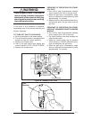
a. Disconnect ignitor leads at AMP receptacle
and check for 120 volts at the plug during
ignition sequence.
b. Replace ignition control if 120 volts is not
available at AMP plug during ignition se-
quence.
120 Volts Is Available At AMP Plug—
Ignitor Does Not Heat Up
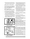
a. Disconnect power to the furnace.
b. Disconnect AMP plug to the ignitor, and
check ignitor resistance with an ohm meter.
Set on RX1 scale.
• Normal reading should be 40 - 75 ohms.
• If above or below this rating at room tem-
perature change ignitor.
c. Check for continuity from ignitor receptacle
to burner.
Main Flame Ignites—
Burner Locks Out
a. Ignition control is not properly grounded.
b. Defective ignition control.
c. Improper polarity of 120 volt power supply.
d. Ignitor has hairline crack.
e. Improper gas pressure or burner air adjust-
ment is not allowing flame to contact ignitor tip
for flame rectification.
f. Misaligned ignitor does not allow flame to
contact ignitor tip for flame rectification.
Burner Short Cycling —-
Thermostat Calls for Heat, Limit Switches
Closed
a. Check for polarity.
b. Check ground.
c. Check flue.
d. Check combustion air.
e. Check gas pressure.
f. Check orifice.
g. Check the position of ignitor, a normal read-
ing should be 40-75 ohms.
24 Volts Supplied To Gas Valve During
Ignition —
No Main Gas Flow
a. Gas valve may be defective. Replace if
necessary.
b. Gas piping may be plugged. Check for
adequate gas supply to gas valve at union.
Burner Operates—
Insufficient Heat
a. Check thermostat for proper setting and
location. Thermostat should not be located
where it will be affected by another heat
source.
b. Check for clean filter and proper air flow.
c. Check burner for proper gas firing rate.
d. Be sure unit is not undersized for its thermal
load.
e. Check thermostat anticipator. The nominal
anticipator setting is 0.4.
Burner Flame Without Motor Running
a. Gas valve stuck open, check gas valve for
proper operation (replace if necessary) and
inspect heat exchanger.
b. Check for 115 volts to the combustion blower
motor; replace if necessary.