


25
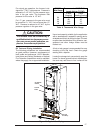
2. Limit Control - This furnace is protected by
two high temperature safety limit switches.
The auxiliary (upper) limit switch and the high
temperature (lower) limit switch are auto-
matic reset types. If either limit trips, the
burner will shut off. If either limit switch trips
off again soon after resetting, set the furnace
On-Off switch to the “OFF” position and call
your authorized serviceman.
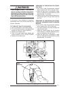
3. Gas Valve - The gas valves for the gas
furnaces are a 100% shut-off type and will fail
safe if for some reason the gas is turned off.
The valve is a “step-open” type for M1G*-
models and “slow-open” for M1M*- and M1B*-
models which means it opens to a “low-fire”
position, and after a few seconds, “steps-
open” to “high-fire.”
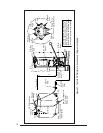
4. Roll Out Switch - (M1G* - 056 & 070) The
furnace is protected by a manual reset safety
switch located on the bottom left hand side of
the combustion pipe.
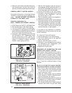
5. Oil Burner Primary Control - The primary
control for oil gun furnaces starts the burner,
monitors a safe operating cycle, and shuts
the burner off at the end of a heating cycle.
The control uses a light sensing transducer
to determine if fuel ignition has been suc-
cessfully attained. If ignition is not attained by
the end of the safety ignition timing period, the
control shuts the burner off and enters “lock-
out.”
6. a. Summer Cooling - (H Series): Your fur-
nace is equipped to operate the circulating
fan only. Turn the Fan On-Auto switch to the
“ON” position during warm weather. The
blower will now operate to circulate air in your
home through the duct system.
b. Summer Cooling - (A, B, C, & D Series):
Your furnace is A/C ready, equipped with A/
C relay and transformer. The unit is equipped
to use a 4-wire thermostat. When using a 5-
wire thermostat, RC and RH should be
jumped (see instructions included with ther-
mostat).
17. SERVICE GUIDE
BURNER ADJUSTMENTS
Burner settings and adjustments are made at
the factory. However, these settings may
change during shipping, handling, and installa-
tion. Therefore the following items should be
checked and readjusted if necessary.
Atmospheric Gas with Standing Pilot and Direct
Ignition Furnaces, Including Gas Gun.
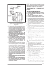
a. Gas Pressure
The gas pressure can be checked with a
manometer at the pressure tap located on
the side of the gas valve. The gas valve
pressure regulator can be adjusted by re-
moving the regulator selector stack and
turning the slotted insert located directly
under the selector stack. The regulator
selector stack must be secured in place
before each pressure reading is taken.
Natural gas manifold pressure should be 3.5"
W.C. and L.P. gas manifold pressure should
be 10" W.C. Replace the gas pressure tap
plug on the gas valve.
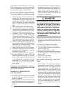
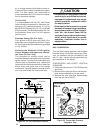
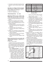
b. Pilot Flame (Standing Pilot Only)
The pilot flame can be adjusted by turning the
pilot adjustment screw, located on top of the
gas valve (See Figure 29). The pilot flame
height should be between 3/4” and 1.” The
flame tip should be visible just above the pilot
bracket when viewed through the observa-
tion door. The same pilot orifice is used with
both natural and L.P. gas.
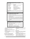
COMBUSTION AIR
In order for the flame to burn efficiently, it must
receive adequate combustion air. The amount
of combustion air required will vary depending
on altitude, actual B.T.U. content of the fuel
being used, gas pressure, conversion to an-
other gas and other factors. The burner flame
should be observed and any necessary adjust-
ments made before the furnace is placed into
service. See Table 9 for Factory Air settings.
Gas Gun
Combustion air adjustment is made to the main
burner by loosening the lock nut on the plastic
air shutter, located on the side of the plastic
burner air inlet box. Move the threaded rod to
a smaller number (counterclockwise) for less
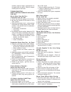
Table 9.
Factory Combustion
Air Settings
M1B* - 066 = 3.5
M1B* - 086 = 4.0
M1S* - 066 = 3.0
M1S* - 086 = 5.5