


11
11. INSTALLATION
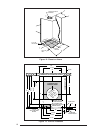
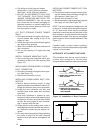
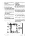
Required floor, ceiling, and roof cut-out open-
ings must be carefully located to avoid misalign-
ment of the furnace and Roof Jack (see Figures
12 & 13). Installation procedures are suggested
for typical furnace installations and need not be
followed in the exact listed sequence.
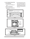
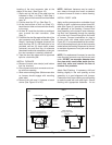
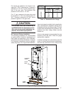
CUT OUT FLOOR OPENING & FUEL LINE
HOLE
a. Determine center of closet or alcove (Figure
13).
b. Locate center of the floor opening, measured
10" from the rear wall, and mark cut-out
measuring approximately 14-1/2" by 14-1/2"
(± 1”) for model duct connector used (refer
to Figures 10 & 11).
c. Locate center of fuel line hole, measured 23-
1/4" from the rear wall and 6-5/8" to the left of
center of the floor cut-out (See Figure 12) or
5-1/4" to the left of center of the floor cut-out,
or for entry through right-side of furnace
measured 9" to the right of center of the floor
cut-out.
d. Cut out floor opening and one fuel line hole.
!
IMPORTANT:
Refer to the installation instructions
provided with optional air conditioning
packages when installing furnaces with
optional cooling coil cabinet or with
optional C***-series indoor coils.
CUT OUT CEILING AND ROOF OPENINGS
a. Locate center of Roof Jack opening, mea-
sured 13 1/2" from the rear wall of closet or
alcove along the center line of furnace and
floor opening. (See Figure 13)
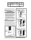
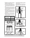
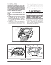
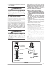
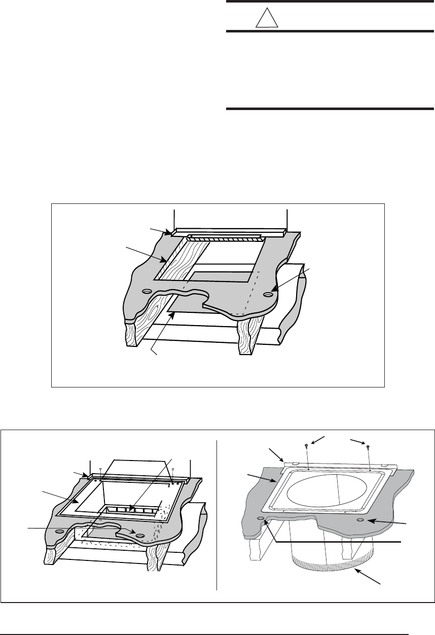
Figure 15. Duct Connector
Figure 14. Mounting Plate
REAR WALL
MOUNTING
PLATE
FLOOR
OPENING
FUEL
LINE
HOLES
SUPPLY AIR DUCT
CUT DUCT OPENING
1/16TH. LARGER THAN
DUCT CONNECTOR
REAR WALL
SUPPLY AIR DUCT
FUEL
LINE
HOLES
M
OUNTING
PLATE
FLOOR
OPENING
UNDER DUCT OPENING
Non-Platinum Series
Platinum Series
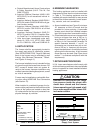
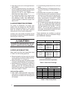
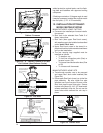
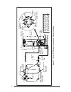
DUCT
CONNECTOR
MOUNTING
PLATE
SCREWS
FUEL
LINE
HOLES
14” SUPPLY
CONNECTION