


7
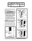
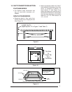
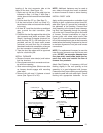
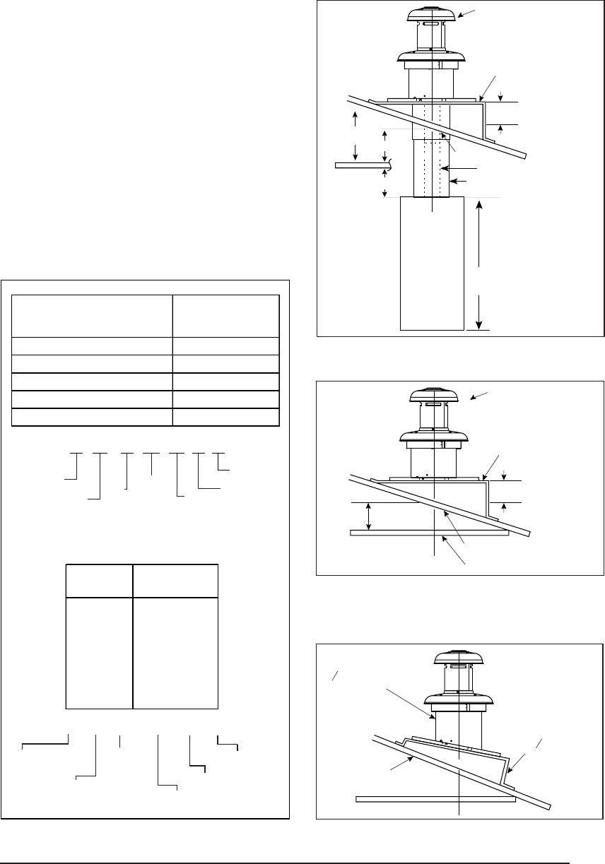
ROOF JACK
SLANT DECK
FLASHING
PITCHED
ROOF
CEILING
CEILING CAVITY
ROOF OPENING
CEILING OPENING
"X" (SEE TABLE 6)
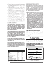
S O T 27 45 -5
S= SLAT FLASHING
F= FLAT FLASHING
O= TYPE; STANDARD
H= HIGH WIND
A= ARCTIC ROOF JACK
T= TRANSIT
MODE
TYPE
MIN. ADJ.
LENGTH
MAX. ADJ.LENGTH
5 = 5" FLUE DIA.
MODEL APPROX. ADJ.
NUMBER LENGTHS*
BELOW FLASHING
FO1323 -5 13" - 23"
FO2343 -5 23" - 43"
SO1835 -5 18" - 35"
SO2447 -5 24" - 47"
SO3263 -5 32" -63"
SO4895 -5 48" - 95"
SOT2442 -5 24" - 42"
SOT2745 -5 27" - 45"
SOT4581 -5 45" - 81"
FOT2846 -5 28" - 46"
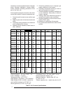
Table 5. Roof Jack Assemblies
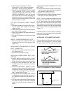
a. Regardless of the location, the return air
opening into the closet shall not be less than
specified in the appliance’s listing.
b. Means shall be provided to prevent inadvert-
ent closure by a flat object placed over the
return air opening when it is located in the floor
of the closet (versus the vertical front or side
wall).
c. The cross-sectional area of the return duct
system leading into the closet, when located
in the floor or ceiling shall not be less than 235
square inches (or 390 square inches for 5 ton
ready M1 Furnaces).
d. The total free area of openings in the floor or
ceiling registers serving the return air duct
system must be at least 235 sq. in. At least
one register should be located where it is not
likely to be covered by carpeting, boxes and
other objects.
e. Materials located in the return duct system
must have a flame spread classification of
200 or less. This includes a closet door if the
furnace is in a closet.
f. Noncombustible pans having 1" upturned
flanges are located beneath openings in a
floor duct system.
g. Wiring materials located in the return duct
system shall conform to Articles 300-22 of
the National Electrical Code (ANSI C1/NFPA-
70).
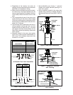
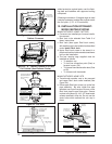
SSAW
T
27
47 - 2
AW= ALL WEATHER
FLASHING
PITCH/12" RISE
0=FLAT
2=2.5/12
4=4/12
MIN. ADJ.
LENGTH
F=
S=
FLAT FLASHING
SLANT FLASHING
TYPE:
BLANK=NON-TRANSIT
T= TRANSIT MODE
MAX. ADJ.
LENGTH
FLUE STEEL TYPE
A= ALUMINIZED
S=STAINLESS
All Weather Roof Jack Assemblies
Approx. Length
Model Number Below Flashing
(F,S)AW(T)1523-(0,2,4)(A,S) 15" - 23"
(F,S)AW(T)2135-(0,2,4)(A,S) 21" - 35"
(F,S)AW(T)2747-(0,2,4)(A,S) 27" - 47"
(F,S)AW(T)3563-(0,2,4)(A,S) 35" - 63"
(F,S)AW(T)5195-(0,2,4)(A,S) 51" - 95"
Figure 6. Roof Jack Assemblies
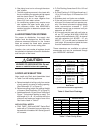
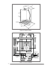
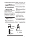
ROOF JACK
SLANT DECK
FLASHING
PITCHED
ROOF
CEILING
CEILING
CAVITY
ROOF
OPENING
"X" (SEE TABLE 1)
Flue Pipe
Combustion
Air Pipe
56" or 76"
Furnace
"A"
"B"
Figure 7. Example of Flat Jack
with Flashing
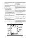
Figure 8. Example of 2½/12 Slant Jack
with Flashing
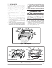
5/12 ROOF SLOPE
2
SLANT DECK
/12
1
2
R
OOF JACK WITH
2
F
LASHING
/12 SLANT
1
2