


2 - 46
2 SYSTEM CONFIGURATION
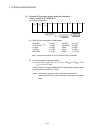
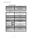
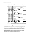
2.4.4 Q172LX Servo external signals interface module
Q172LX receives external signals (servo external signals) required for positioning
control.
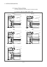
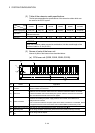
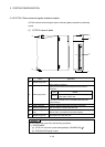
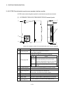
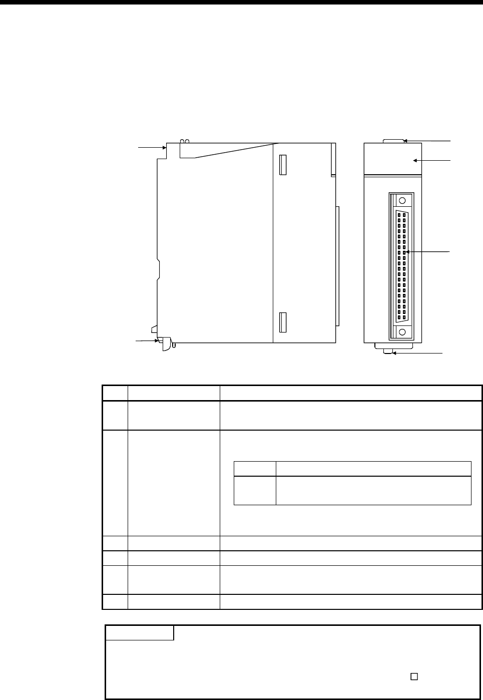
(1) Q172LX name of parts
5)
6)
2)
4)
3)
1)
CTRL
Q172LX
Q172LX
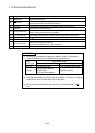
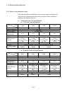
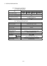
No. Name Application
1) Module fixing hook
Hook used to fix the module to the base unit.
(Quick release installation)
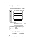
Display the servo external input status from the external
equipment.
LED Details
0 to 1F
Indicates to display the servo external signal
input status of each axis.
2) Mode judging LED
This LED is not turned on if it is not set the Q172LX in the
system settings.
3) CTRL connector The servo external signal input connector of each axis.
4) Module loading lever Used to install the module to the base unit.
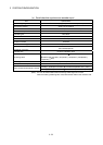
5)
Module fixing screw
hole
Hole for the screw used to fix to the base unit.
(M3×12 screw : Purchase from the other supplier)
6) Module fixing hook Hook used to fix to the base unit.
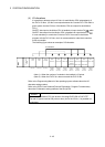
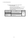
POINT
Mode judging LED turns ON at the following conditions.
(1) DOG/CHANGE
(a) Q172LX is set on the system setting display of SW6RN-GSV
P.
(b) DOG/CHANGE signal is input.