2 - 29
2 SYSTEM CONFIGURATION
(3) Applications of switches, connectors on Q173CPU(N)/
Q172CPU(N)
No. Name Application
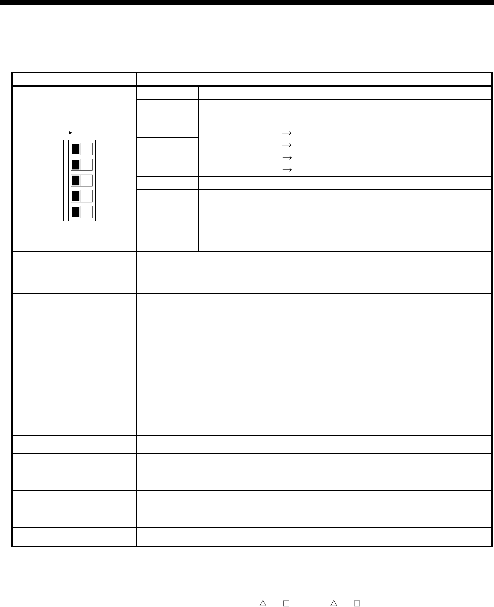
Dip switch 1 Must not be used. (Shipped from the factory in OFF position)
• ROM operating setting (Shipped from the factory in OFF position)
Dip switch 2
Dip switch 3
SW2
OFF
ON
OFF
ON
SW3
OFF
OFF
ON
ON
Mode operated by RAM
Must not be set
Must not be set
Mode operated by ROM
Dip switch 4 Must not be used. (Shipped from the factory in OFF position)
13)
Dip switches
1
2
3
4
5
ON SW
Dip switch 5
(Installation •
ROM writing
switch)
ON : Installation mode • mode written in ROM
OFF : Normal mode (Mode operated by RAM/Mode operated by ROM)
• Turn ON dip switch 5 when installed the operating system software into the
Motion CPU module from the peripheral device. After completing the installation,
move to switch and re-start.
14) RUN/STOP switch
Move to RUN/STOP.
RUN : Motion SFC program(SV13/SV22)/Motion program(SV43) is started.
STOP : Motion SFC program(SV13/SV22)/Motion program(SV43) is stopped.
15)
RESET/L.CLR switch
(Note-1)
(Momentary switch)
RESET : Set the switch to the
"
RESET
"
position once to reset the hardware.
Applies a reset after an operation error and initialized the operation.
L.CLR : Clear the latch area all data which set with the parameters.
(LATCH CLEAR also clears data outside the latch area at this time.)
Latch clear operating method
1) Set the
"
RUN/STOP
"
switch to
"
STOP
"
.
2) Move the
"
RESET/L.CLR
"
switch to
"
L.CLR
"
several times until the
"
M. RUN LED
"
flickers.
(
"
M. RUN LED
"
flickers : Latch clear completed. )
3) Move the
"
RESET/L.CLR
"
switch to
"
L.CLR
"
once more. (
"
M. RUN LED
"
turn off.)
16) Module fixing screw hole Hole for the screw used to fix to the base unit. (M3×12 screw : Purchase from the other supplier)
17) Module fixing hook Hook used to fix to the base unit
18) CN1 connector
(Note-2)
Connector connect between Motion CPU module and servo amplifier
19) CN2 connector Connector connect between personal computer via SSCNET
20) TU connector
(Note-3)(Note-4)
Connector connect between Motion CPU module and teaching unit
21) Cooling fan connector
(Note-5)
Connector connect between Motion CPU module and Cooling fan unit (Q170 FAN)
22) Cooling fan unit
(Note-5)
Cooling fan unit(Q170 FAN) designed exclusively for Motion CPU module
(Note-1) : It is not possible to reset the Multiple CPU system by each of the PLC CPU/Motion CPU No.2 to 4.
If it is reset, other CPU occurred to stop of the overall Multiple CPU system where “MULTI CPU DOWN (Error code : 7000).
The overall Multiple CPU system reset is resetting the CPU No.1 of PLC CPU.
(Note-2) : For example of the Q173CPU(N), the connector CN1 divide signals allocated each of SSCNET SYSTEM 1 to 4.
The Dividing unit (Q173DV) or the Dividing cable (Q173J2B
CBL M/Q173HB CBL M) between the Motion CPU and
servo amplifiers divide signals allocated in CN1 of the Q173CPU(N) into each of the four systems.
(Note-3) : Q173CPUN-T/Q172CPUN-T only. Teaching unit corresponds to only Japanese.
(Note-4) : When connecting the teaching unit, be sure to use the cable which adjusts to the model name of teaching unit.
(Note-5) : Q173CPU/Q172CPU only. Teaching unit corresponds to only Japanese.


