


4 - 12
4 INSTALLATION AND WIRING
4.3 Installation of the Serial Absolute Synchronous Encoder
This section described instructions for handling the Serial absolute synchronous
encoder (MR-HENC/Q170ENC).
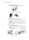
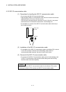
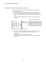
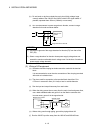
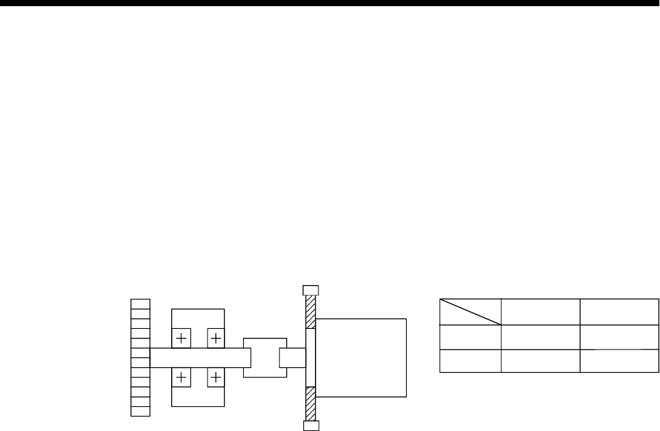
(1) If the serial absolute synchronous encoder is linked to a chain, timing belt, or
gears, the machine rotating shaft should be supported by a separate bearing
and connected to MR-HENC/Q170ENC through a coupling. Ensure that excessive
force
(greater than the permitted shaft load) is not applied to the shaft of MR-HENC/
Q170ENC.
Table 4.1 Permitted Shaft Loads
Gear
Coupling
Radial direction
Thrust direction
Up to 98N
Up to 49N
MR-HENC/Q170ENC
Bearing
MR-HENC
Q170ENC
Up to 19.6N
Up to 9.8N
Fig. 4.1 Example of Encoder Linked to a Gear
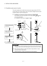
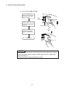
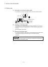
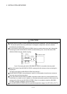
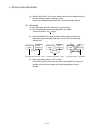
(2) Large errors in eccentricity and angle of deviation during installation can apply
an excessive force to the MR-HENC/Q170ENC shaft, which can cause
deterioration in
performance drastically reduce encoder service time.
Minimize loads applied to the shaft such that they lie within the permitted shaft
load range.