App - 16
A
PPENDICES
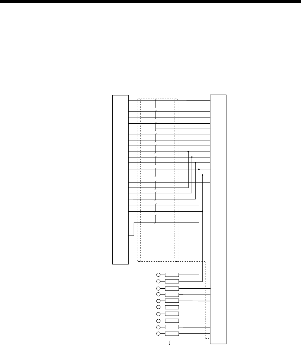
(2) Q170TUD3CBL3M
(a) Connection diagram
When fabricating a cable, use the recommended wire and connector
given on APPENDIX 1.3, and make the cable as show in the following
connection diagram. Make the cable within 3m(9.84ft.).
DB-20962
BAL 15
BA 2
SG 22
Q170TUD3CBL3M
HDR-E26-LPA5
HDR-E26FG1
DB-25SF-N
SG 9
5V 7
5V 8
BBL 14
SG 3
SG 10
CBL 17
CB 4
BB 1
5V 6
CA 5
CAL 18
(connector)
(connector case)
(connector)
(cover)
EMG 25
FG 13
AB 11
5V 21
SG 23
SG 16
5V 19
5V 20
SD shell
shell
BAL
BA
SG
5V
5V
BBL
SG
SG
CBL
CB
BB
5V
CA
CAL
FG
AB
5V
16
3
8
13
25
15
7
17
4
2
12
5
18
1
21
20
24
23
19
22
9
6
14
10
11
EMG
SG
EMG2
DC24GE
EMG1
DC24VE
DED2
DC24GD
DED1
DC24VD
(Red)
(White)
(Red)
(White)
(Red)
(White)
(Red)
(White)
(Red)
(White)
DC24GD
(Note)
DED2
(Note)
DED1
DC24VE
DC24VD
EMG1
EMG2
(Note)
DC24GE
(Note)
SD
(Note) : These terminals are used to construct a double circuit by external safety circuit.
Please contact your nearest Mitsubishi sales representative for a double circuit.
:Twisted pair cable


