6 - 16
6 INSPECTION AND MAINTENANCE
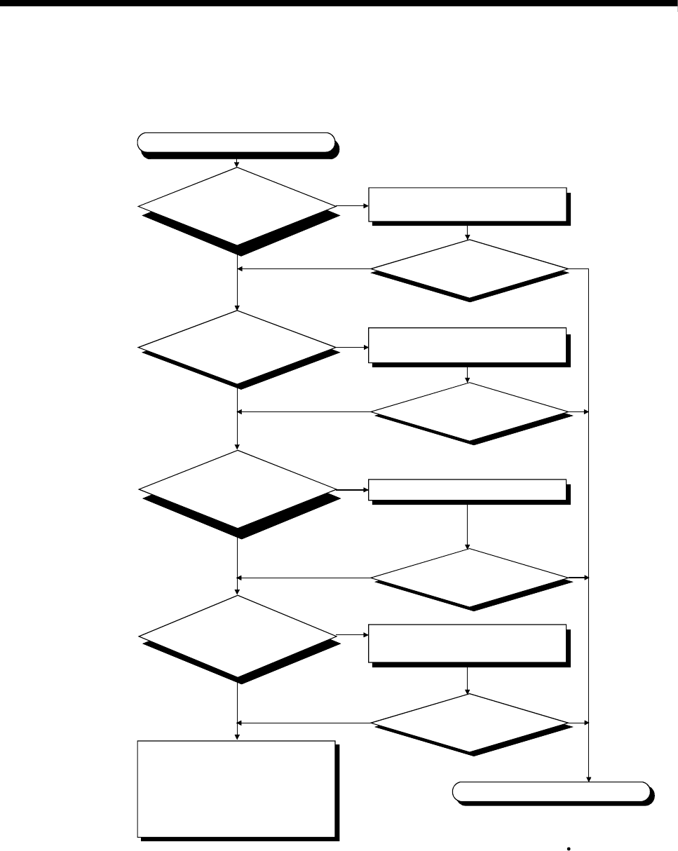
(b) Flowchart for when "MODE" LED is turned off.
The following shows the flowchart when the "MODE" LED is turned off at
the power supply ON.
"MODE" LED is turned off
Check the wiring and turn on the
all power supplies.
Completion
NO
YES
NO YES
YES
NO YES
NO
NO
YES
YES
NO
NO YES
"RESET" position
Neutral position
(Note) : Lit (green) : Normal
Lit (orange) : Installation mode mode written in RO
Is the power
supply for all the power
supplies modules turned on?
Is the wiring of the power supply
module correct?
Is "MODE" LED
turned on?
Is the LED of
power supply
module turned on?
Replace the power supply module,
and check that the LED is ON.
Is "MODE" LED
turned on?
Connect the extension cable correctly.
Is "MODE" LED
turned on?
Is the
connecting direction of
extension cable correctly?
(Isn't IN- IN or OUT-OUT
connection?)
Is the
CPU module of the No.1
and corresponding CPU module
RESET/L.CLR switch in the
neutral position?
Set the RESET/ L.CLR switch in the
neutral position.
Is "MODE" LED
turned on?
H/W error
Confirm the operation in the order
starting from the minimum system.
Explain the error symptom and get
advice from our sales representative
for the modules with failure.


