


6
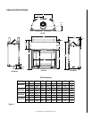
NOTE: DIAGRAMS & ILLUSTRATIONS NOT TO SCALE.
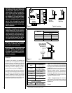
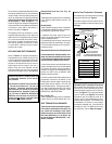
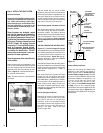
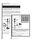
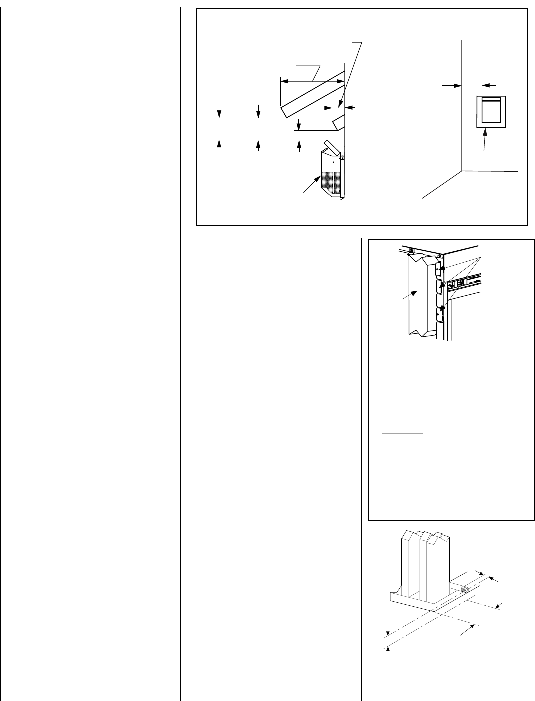
The fireplace should be secured to the side framing
members using the unit's nailing flanges - one top
and bottom on each side of the fireplace front. See
Figure 6.
Use 8d nails or their equivalent.
Unit Being Secured by Its Nailing
Flanges to the Framing
Figure 6
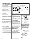
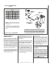
Figure 5 -
Side Elevation View
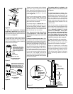
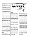
Figure 7
Step 2. ROUTING GAS LINE
Route a 1/2" (13 mm) gas line along the inside
of the left side framing as shown in
Figure 7
.
Gas lines must be routed, constructed and
made of materials that are in strict accordance
with local codes and regulations.
All appliances are factory-equipped with a flex-
ible gas line connector and 1/2 inch shutoff
valve. (See step 6 on page 22).
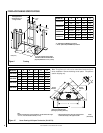
Step 1. FRAMING
Frame these appliances as illustrated in
Figure 9
on page 8,
unless the appliance is to be installed
in a corner
.
See
Figure 10 on page 8
for corner framing
installations. All framing details must allow for a
minimum clearance to combustible framing mem-
bers as shown in
Table 2 on page 4
.
If the appliance is to be elevated above floor level,
a solid continuous platform must be constructed.
Headers may be in direct contact with the appli-
ance top spacers but must not be supported by
them or notched to fit around them. All construc-
tion above the appliance must be self supporting,
DO NOT use the appliance for structural support.
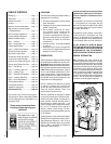
TYPICAL INSTALLATION SEQUENCE
The typical sequence of installation follows,
however, each installation is unique resulting in
variations to those described.
See the page numbers references in the follow-
ing steps for detailed procedures.
Step 1. (page 6) Construct the appliance fram-
ing. Position the appliance within the framing
and secure with nailing brackets.
Step 2. (page 6) Route gas supply line to
appliance location.
Step 3. (page 10) Install the vent system
and exterior termination. Install additional
restrictor, if needed.
Step 4. (page 21) Field Wiring
a. Millivolt Appliances – The operating control
switch is factory installed.
b. Electronic Appliances – Connect 120 Vac
electrical power to the appliance receptacle.
Step 5. (page 22) Make connection to gas
supply.
Step 6. (page 23) Install the logs and glow-
ing embers.
Step 7. (page 23) Checkout appliance operation.
Step 8. (page 23) Install glass door frame
assembly.
Step 9. (page 24) Adjust burner to ensure
proper flame appearance.
DETAILED INSTALLATION STEPS
The appliance is shipped with all gas controls
and components installed and pre-wired. Re-
move the shipping carton, exposing the front
glass door. Remove the bottom panel by lifting
and pulling it towards the front.
Open the two latches (located under the firebox
floor) securing the glass door. Remove the
door by tilting it outward at the bottom and
lifting it up. Set the door aside protecting it from
inadvertent damage.
See Figure 39 on page 23.
Note: The nailing flanges, combustible members
and screw heads located in areas directly adjacent
to the nailing flanges, are EXEMPT from the 1”
clearance to combustible requirements for the
firebox outer wrapper. Combustible framing may be
in
direct contact with the nailing flanges and may
be located closer than 1” from screw heads and the
firebox wrapper in areas adjacent to the nailing
flanges. Frame the opening to the exact dimensions
specified in the framing details of this manual.
Nailing Flanges Are
Provided At All Four
Corners At 5/8”, 1/2”
And Flush Settings
Side
Framing
Unit
Nailing Flange
Left Side Top Corner of Fireplace Shown
(Right Side Requirements the Same)
Unit Being Secured By Its Nailing Flanges
To The Framing
Left Side
Front Corner of
Fireplace Framing
4-3/4"
(121 mm)
2-1/4"
(57 mm)
6-1/2"
(165 mm)
3"
(76 mm)
12"
(305 mm)
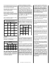
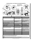
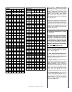
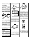
Combustible Projection greater
Horizontal Vent Termination Clearances
Combustible Projection
2-1/2
inches or less in length
18"
(457 mm)
Ventilated
Soffit
Unventilated
Soffit
than 2-1/2 inches in length
Termination Kit
Termination Kit
All horizontal terminations
may be located as close as
6” (152mm) to any
(non-combustible and
combustible) exterior
sidewall. This distance
may be decreased to 2”
(51mm) for non-n-
combustible exterior
sidewalls only, if the
SV4.5HT-2 termination
is used.