


NOTE: DIAGRAMS & ILLUSTRATIONS NOT TO SCALE.
11
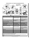
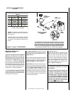
Maintain a minimum 1" (25 mm) clearance
to combustible materials for all vertical
vent elements.
Clearances for horizontal vent elements are
1" (25 mm) at the sides and 1" (25 mm) on
the bottom. Clearances above horizontal
vent elements are 3" (76 mm) for all models
and all applications.
Exception: Clearance
is 5" (127 mm) for MPLDV35, MPLDV40 &
MPLDV45, when the center line of the hori-
zontal run is less than 48" (1219 mm) above
the fireplace top wrapper surface.
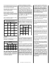
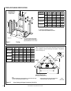
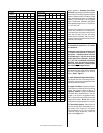
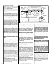
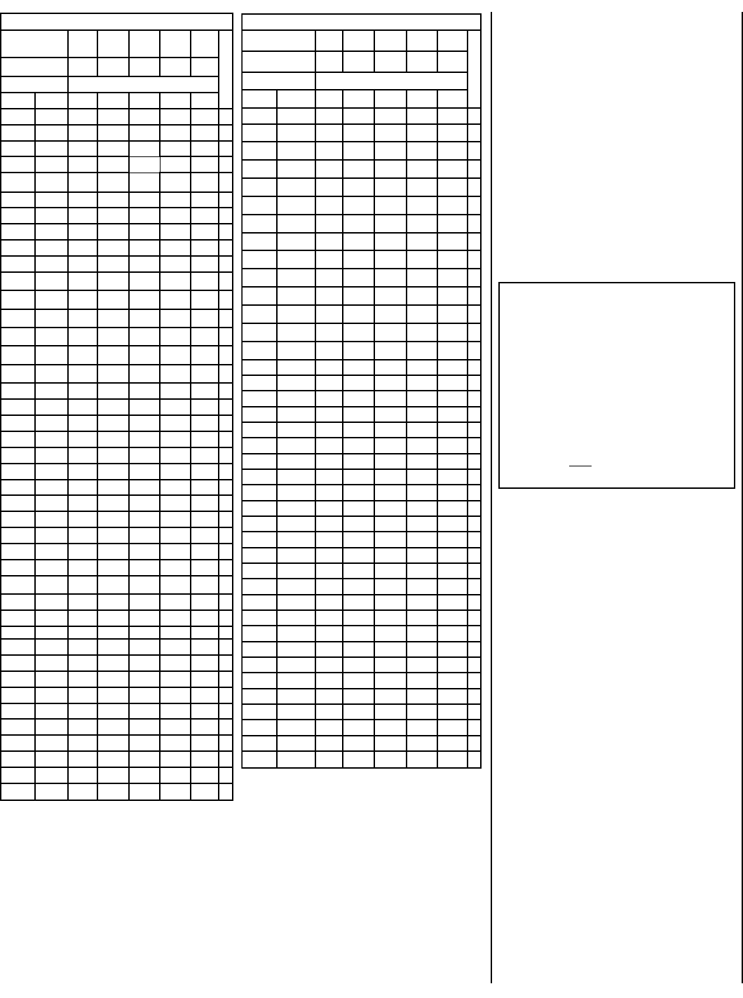
TRAHCHTGNELNOITCESTNEV
lanimoN
htgneLnoitceS
)sehcni(
621426384
T
O
T
A
L
Q
T
Y
noitceSteN
)sehcni(htgneL
2/1-42/1-012/1-222/1-432/1-64
tneVfothgieHsnoitceStneVforebmuN
sehcnitf
5.4573.0100001
957.0200002
5.01578.0010001
5152.1110002
5.91526.12100
0
3
1257.1020002
5.22578.1001001
5.52521.2120003
5.13526.2030003
5.43578.2000101
5.73521.3111003
5.34526.3021003
5457.3002002
5.64578.3000011
5.94521.4102003
1552.4100012
5.55526.4012003
7557.4001102
6652.5022004
5.76526.5003003
9657.5000202
27 6103004
5.37521.6100203
5.97526.6010203
1857.6000112
095.7021014
5.19526.7002013
3957.7000022
69 8101204
5.79521.8100023
2015.8200024
5.301526.8000303
801 9100304
4115.9020024
71157.9105006
5.811578.9110305
6215.01001304
5.031578.01101305
53152.11006006
8315.11000404
5.931526.11000033
5.241578.11100405
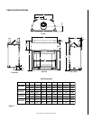
TRAHCHTGNELNOITCESTNEV
noitceSlanimoN
)sehcni(htgneL
621426384
T
O
T
A
L
Q
T
Y
noitceSteN
)sehcni(htgneL
2/1-42/1-012/1-222/1-432/1-64
tneVfothgieHsnoitceStneVforebmuN
sehcnitf
44121100034
0515.21010034
5.451578.21110035
5.061573.31020035
5.271573.41000505
77157.41100506
38152.51010506
6815.51000044
5.091578.51100045
5.691573.61010045
5.502521.71011507
70252.71000606
5.112526.71100607
5.712521.81010607
5.922521.91001607
5.232573.91000055
73257.91100056
5.142521.02000707
6425.02100708
25212010708
46222001708
67232000808
97252.32000066
5.082573.32100809
5.382526.32100067
5.982521.42010067
5.103521.52001067
5.013578.52000909
5135.621009001
5.523521.72000077
0335.72100078
63382010078
54357.8200001001
5.943521.9210001011
27313000088
5.673573.13100089
5.973526.1300011011
5.814578.43000099
32452.531000901
56457.8300000101
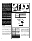
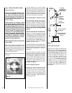
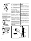
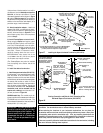
Where required, a telescopic vent section
(SV4.5LA) may be used to provide the installer
with an option in installing in tight and confined
spaces or where the vent run made up of fixed
length pieces develops a joint in a undesirable
location, or will not build up to the required
length. The SV4.5LA Telescopic Vent Section
has an effective length of from 1-1/2" (38 mm)
to 7-1/2" (191 mm).
The SV4.5LA is fitted with a locking inclined
channel end (identical to a normal vent sec-
tion component) and a plain end with 3 pilot
holes. Slip the plain end over the locking
channel end of a standard SV4.5 vent com-
ponent the required distance and secure with
three #8 x 3/8" screws.
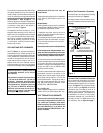
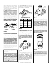
The starter elbow may not be used if a 45 degree
vent run is required directly off of the unit.
Refer to
Detail - Figure 17
.
A. Attach Supplied 45 Degree Starter Elbow -
Slip the plain end with 3 mounting holes over
the locking channel end of the appliance collar
and secure with three screws.
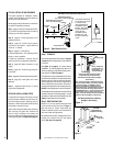
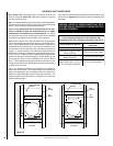
B. Support The Elbows - Support the starter
elbow and the vertical portions of the venting
system with support bracket as shown in
Figure 23
- Detail A, on page 14. Do not use
the starter elbow anywhere else in the vent
system if not used on the appliance collar.
SV4.5 rigid and flex components can be used
directly off the collar. Do not return to rigid
sections after using flex sections in a vent run.
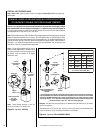
C. Frame ceiling opening - Use a plumb line
from the ceiling above the appliance to lo-
cate center of the vertical run. Cut and/or
frame an opening, 10-1/2" x 10-1/2" (267mm
x 267mm) inside dimensions, about this
center mark (
Figure 14
).