


28
NOTE: DIAGRAMS & ILLUSTRATIONS NOT TO SCALE.
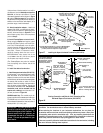
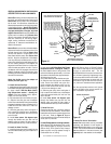
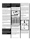
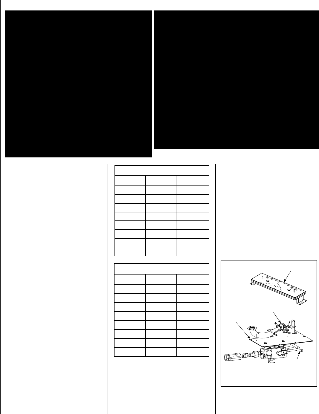
Figure 47
Burner Assembly
Gas Valve
Assembly
Orifice
Air Adjustment
Arm
In Canada:
THE CONVERSION SHALL BE CARRIED OUT
IN ACCORDANCE WITH THE REQUIREMENTS
OF THE PROVINCIAL AUTHORITIES HAVING
JURISDICTION AND IN ACCORDANCE WITH
THE REQUIREMENTS OF THE CAN1-B149.1
AND .2 INSTALLATION CODE.
LA CONVERSION DEVRA ÊTRE EFFECTUÉE
CONFORMÉMENT AUX RECOMMANDATIONS
DES AUTORITÉS PROVINCIALES AYANT
JURIDICTION ET CONFORMÉMENT AUX
EXIGENCES DU CODE D'INSTALLATION CAN1-
B149.1 ET.2.
Gas conversion kits are available to adapt your
appliance from the use of one type of gas to the
use of another. These kits contain all the neces-
sary components needed to complete the task
including labeling that must be affixed to en-
sure safe operation.
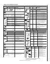
Kit part numbers are listed here and the following
steps detail the conversion procedure.
Step 1. Turn off the gas supply to the appliance.
Step 2. Carefully remove the logs. Exercise
care so as not to break the logs.
Step 3. Refer to
Figure 47
.
Remove the burner assembly with attached
venturi tube.
GAS CONVERSION KITS
WARNING: THIS CONVERSION KIT SHALL BE
INSTALLED BY A QUALIFIED SERVICE AGENCY IN
ACCORDANCE WITH THE MANUFACTURER'S IN-
STRUCTIONS AND ALL APPLICABLE CODES AND
REQUIREMENTS OF THE AUTHORIZED HAVING
JURISDICTION. IF THE INFORMATION IN THESE
INSTRUCTIONS IS NOT FOLLOWED EXACTLY, A
FIRE, EXPLOSION OR PRODUCTION OF CARBON
MONOXIDE MAY RESULT CAUSING PROPERTY
DAMAGE, PERSONAL INJURY OR LOSS OF LIFE.
THE INSTALLATION IS NOT PROPER AND COM-
PLETE UNTIL THE OPERATION OF THE CONVERTED
APPLIANCE IS CHECKED AS SPECIFIED IN THE
OWNER INSTRUCTIONS SUPPLIED WITH THE KIT.
THE QUALIFIED SERVICE AGENCY PERFORMING
THIS INSTALLATION ASSUMES RESPONSIBILITY
FOR THIS CONVERSION.
AVERTISSEMENT: CET ÉQUIPEMENT DE CONVERSION
SERA INSTALLÉ PAR UNE AGENCE QUALIFIÉE DE SERVICE
CONFORMÉMENT AUX INSTRUCTIONS DU FABRICANT ET
TOUTES EXIGENCES ET CODES APPLICABLES DE
L'AUTORISÉS AVOIR LA JURIDICTION. SI L'INFORMATION
DANS CETTE INSTRUCTION N'EST PAS SUIVIE
EXACTEMENT, UN FEU, EXPLOSION OU PRODUCTION DE
PROTOXYDE DE CARBONE PEUT RÉSULTER LE DOMMAGES
CAUSER DE PROPRIÉTÉ, PERTE OU BLESSURE
PERSONNELLE DE VIE. L'AGENCE QUALIFIÉE DE SERVICE
EST ESPONSABLE DE L'INSTALLATION PROPRE DE CET
ÉQUIPMENT. L'INSTALLATION N'EST PAS PROPRE ET
COMPLÉTE JUSQU'À L'OPÉRATION DE L'APPAREIL
CONVERTI EST CHÉQUE SUIVANT LES CRITÈRES ÉTABLIS
DANS LES INSTRUCTIONS DE PROPRIÉTAIRE
PROVISIONNÉES AVEC L'ÉQUIPEMENT.
tiKnoisrevnoCsaGlarutaNotenaporP
.oNledoMepyTtinU.oNgolataC
03VDLPMtlovillim5616H
53VDLPMtlovillim8696H
04VDLPMtlovillim95L58
54VDLPMtlovillim26L58
03VDLPMcinortcele0716H
53VDLPMcinortcele4796H
04VDLPMcinortcele2716H
54VDLPMcinortcele3716H
Millivolt Appliances
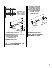
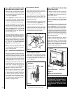
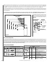
Step 4. SIT Systems - Refer to
Figure 48 on
page 29
and the instructions provided with
the kit. Using a Torx T20, remove and discard
the three pressure regulator mounting screws.
Remove the pressure regulator, spring, pop-
pet, diaphragm and bushing. Discard all
removed components.
Ensure the rubber gasket installed on the back
of the replacement pressure regulator is prop-
erly positioned and install the new pressure
regulator using the new screws supplied with
the kit. Tighten screws to 25 In. lb. torque.
tiKnoisrevnoCsaGenaporPoTlarutaN
.oNsledoMepyTtinU.oNgolataC
03VDLPMtlovillim3616H
53VDLPMtlovillim5796H
04VDLPMtlovillim7716H
54VDLPMtlovillim96L58
03VDLPMcinortcele6616H
53VDLPMcinortcele3796H
04VDLPMcinortcele8616H
54VDLPMcionrtcele9616H