


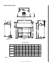
NOTE: DIAGRAMS & ILLUSTRATIONS NOT TO SCALE.
5
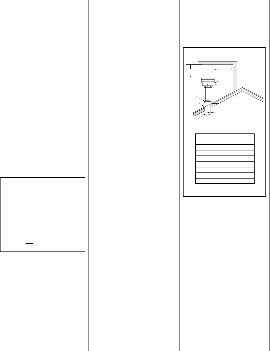
12
X
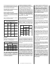
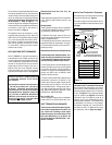
Roof Pitch is X/12
2 FT
MIN.
2 FT MIN.
Lowest
Discharge
Opening
H*
*H = MINIMUM HEIGHT FROM ROOF TO
LOWEST DISCHARGE OPENING OF VENT
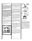
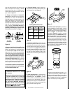
TERMINATION HEIGHTS FOR VENTS ABOVE
FLAT OR SLOPED ROOFS
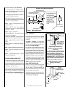
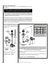
Horizontal Overhang
Vertical
Wall
Vent
Termination
Storm Collar
Concentric
Vent Pipe
Flashing
1 inch (25.4 mm) Minimum
Clearance to Combustibles
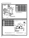
hctiPfooR
H
)teef(
21/6ottalF0.1
21/7ot21/6revO52.1
21/8ot21/7revO5.1
21/9ot21/8revO0.2
21/01ot21/9revO5.2
21/11ot21/01revO52.3
21/21ot21/11revO0.4
Figure 4
Vertical Vent Termination Clearances
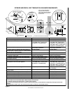
VENT TERMINATION CLEARANCES
These instructions should be used as a guide-
line and do not supersede local codes in any
way. Install vent according to local codes,
these instructions, the current National Fuel
Gas Code (ANSI-Z223.1) in the USA or the
current standards of CAN/CGA-B149.1 and -
B149.2 in Canada.
Terminate multiple vent terminations accord-
ing to the installation codes listed at the top of
this page.
Horizontal Vent Termination Clearances
The horizontal vent termination must have a
minimum of 3" (76 mm) clearance to any over-
head combustible projection of 2-1/2" (64 mm)
or less. See
Figure 5.
For projections exceed-
ing 2-1/2" (64 mm), see
Figure 5
. All horizontal
terminations may be located as close as 6"
(152mm) to any (non-combustible and com-
bustible) exterior sidewall. This distance may
be decreased to 2" (51mm) for non-combus-
tible exterior sidewalls only, if the SV4.5HT-2
termination is used. For additional vent loca-
tion restrictions, refer to
Figure 8 on page 7
.
Terminate single vent caps relative to building
components according to
Figure 4
.
Massachusetts And New York City, NY
Requirements
These appliances are approved for installation
in the following USA locations listed in the
following:
Massachusetts:
These fireplaces are approved for installation
in the US state of Massachusetts if the follow-
ing additional requirements are met-
• Installation and repair must be done by a
plumber or gas fitter licensed in the Common-
wealth of Massachusetts.
• The flexible gas line connector used shall not
exceed 36 inches (92 centimeters) in length.
• The individual manual shut-off must be a T-
handle type valve.
Massachusetts Horizontal Vent Requirements
In the Commonwealth of Massachusetts, hori-
zontal terminations installed less than seven
(7) feet above the finished grade must comply
with the following additional requirements:
• A hard wired carbon monoxide detector with
an alarm and battery back-up must be installed
on the floor level where the gas fireplace is
installed. The carbon monoxide detector must
comply with NFPA 720, be ANSI/UL 2034
listed and be ISA certified.
• A metal or plastic identification plate must be
permanently mounted to the exterior of the
building at a minimum height of eight (8) feet
above grade and be directly in line with the
horizontal termination. The sign must read, in
print size no less than one-half (1/2) inch in
size, GAS VENT DIRECTLY BELOW. KEEP
CLEAR OF ALL OBSTRUCTIONS.
New York City, NY:
These fireplaces are approved for installation
in New York City in the US state of New York.
Maintain a minimum 1" (25 mm) clearance
to combustible materials for all vertical
vent elements.
Clearances for horizontal vent elements are
1" (25 mm) at the sides and 1" (25 mm) on
the bottom. Clearances above horizontal
vent elements are 3" (76 mm) for all models
and all applications.
Exception: Clearance
is 5" (127 mm) for MPLDV35, MPLDV40 &
MPLDV45, when the center line of the hori-
zontal run is less than 48" (1219 mm) above
the fireplace top wrapper surface.
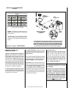
APPLIANCE AND VENT CLEARANCES
Refer To Table 2 for approved clearances to
combustibles for the models covered in this
manual, with the following exception: When the
unit is installed with one side flush with a wall,
the wall on the other side of the unit must not
extend beyond the front edge of the unit. In
addition, when the unit is recessed, the side
walls surrounding the unit must not extend
beyond the front edge of the unit. See
Figure 2
.
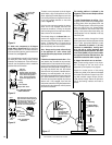
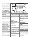
To provide for the lowest possible shelf surface
the venting attached to the top vent should be
routed in a way to minimize obstructions to the
use of the space above the appliance. Do not
insulate the space between the appliance and
the area above it. Refer to
Figure 3
. The
minimum height from the base of the appliance
to the underside of combustible materials used
to construct a utility shelf in this fashion is
shown in the table in
Figure 3
.
The appliance should be mounted on a fully
supported base extending the full width and
depth of the unit. The appliance may be located
on or near conventional construction materi-
als. However, if installed on combustible mate-
rials, such as carpeting, vinyl tile, etc., a metal
or wood barrier covering the entire bottom
surface must be used.