


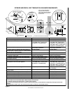
NOTE: DIAGRAMS & ILLUSTRATIONS NOT TO SCALE.
15
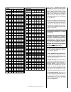
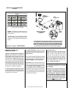
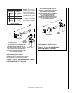
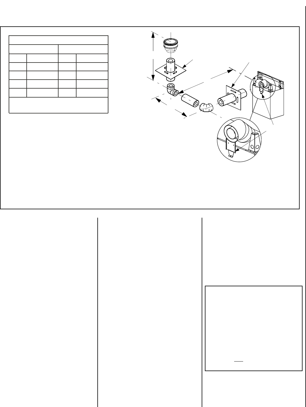
Figure 25 -
Top Vent - THREE ELBOWS
Example: If 20 feet of (H) horizontal vent run is
needed, then 4 feet minimum of (V) vertical vent
will be required.
This table shows a 1 (V) to 5 (H) ratio. For every
1 foot of (V) vertical, you are allowed 5 feet of (H)
horizontal run, up to a maximum horizontal run of
20 feet.
TABLE B
H +
H
1
Maximum
V Minimum
feet feet
5
(1.524)
1
(0.305)
10
(3.048)
2
(0.610)
15
(4.572)
3
(0.914)
20
(6.096)
4
(1.219)
H + H
1
= 20 feet (6.096 m) Max.
V
+ H + H
1
= 40 ft. (12.192 m) Max.
(meters) (meters)
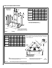
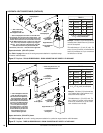
HORIZONTAL (OUTSIDE WALL)
TERMINATION SYSTEM
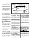
Figures 26, and Figures 29 to 32 on pages 18
and 19
and their associated Horizontal Vent
Table illustrate the various horizontal venting
configurations that are possible for use with
these appliances. Secure Vent pipe applica-
tions are shown in these figures; Secure Flex
pipe may also be used. A Horizontal Vent Table
summarizes each system’s minimum and maxi-
mum vertical and horizontal length values that
can be used to design and install the vent
components in a variety of applications.
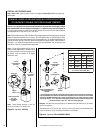
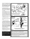
A. Attach Supplied 45 Degree Starter Elbow
- Slip the plain end with 3 mounting holes over
the locking channel end of the appliance collar
and secure with three screws.
Both of these horizontal vent systems terminate
through an outside wall. Building Codes limit or
prohibit terminating in specific areas. Refer to
Figure 8
on page 7 for location guidelines.
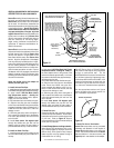
Secure Vent SV4.5 direct vent system compo-
nents are unitized concentric pipe compo-
nents featuring positive twist lock connection,
(
refer to Figure 15
and 16
on page 12). All of
the appliances covered in this document are
fitted with collars having locking inclined chan-
nels. The dimpled end of the vent components
fit over the appliance collar to create the posi-
tive twist lock connection.
C. Plan the vent run -
Analyze the vent routing and determine the
types and quantities of sections required
4-1/2" (114 mm), 10-1/2" (267 mm), 22-1/2"
(572 mm), 34-1/2" (876 mm) and 46-1/2"
(1181 mm) net section lengths are available.
Plan the vent lengths so that a joint does not
occur at the intersection of ceiling or roof
joists. Make allowances for elbows as indi-
cated in
Figure 18 on page 13
.
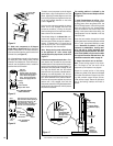
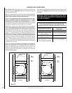
H
1
H
V
*Ceiling
Firestop/Spacer
(SV4.5VF)
**Wall
Firestop/Spacer
*When using Secure Flex,
use Firestop/Spacer
SF4.5VF
Support
Bracket
Detail View
**Use Firestop/Spacer SV4.5HF or SF4.5HF when using Secure Vent or Secure
Flex respectively. Use Firestop/Spacer SV4.5HF5 or SF4.5HF5 when using
Secure Vent or Secure Flex on horizontal vent runs for the MPLDV35/40/45
with a center line lower than 48” (1219 mm) above the fireplace top wrapper
surface. In all cases the firestop/spacer provided with the termination may
be used with the termination, frame to 5” clearance where applicable.
VERTICAL VENT FIGURES/TABLES
(continued)
Maintain a minimum 1" (25 mm) clearance
to combustible materials for all vertical
vent elements.
Clearances for horizontal vent elements are
1" (25 mm) at the sides and 1" (25 mm) on
the bottom. Clearances above horizontal
vent elements are 3" (76 mm) for all models
and all applications.
Exception: Clearance
is 5" (127 mm) for MPLDV35, MPLDV40 &
MPLDV45, when the center line of the hori-
zontal run is less than 48" (1219 mm) above
the fireplace top wrapper surface.
B. Support The Elbows - Support the starter
elbow and the horizontal portions of the vent-
ing system with support bracket as shown in
Figure 29 to 32
.