


12
NOTE: DIAGRAMS & ILLUSTRATIONS NOT TO SCALE.
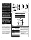
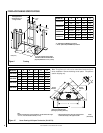
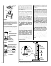
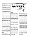
10 1/2” Min.
(267 mm)
10 1/2” Min.
(267 mm)
Figure 14
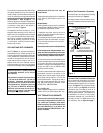
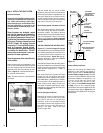
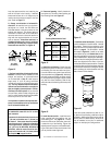
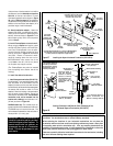
Align the dimple (four places) of the
upper vent section with the opening of
the locking incline channel on the
lower vent section. Twist vent
component clockwise to engage and
seal until arrow and dimple align.
Locking
Incline Channel
Dimple
Arrow
Connected
Vent Sections
Vent / Vent Section
Connection
Arrow
Arrow
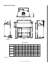
Figure 15
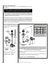
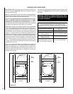
Figure 16
This seating position is indicated by the
alignment of the arrow and dimple as shown
in
Figure 16.
F. Install firestop/spacer at ceiling - When
using Secure Vent, use SV4.5VF firestop/spacer
at ceiling joists; when using Secure Flex, use
SF4.5VF firestop/spacer. If there is living space
above the ceiling level, the firestop/spacer
must be installed on the bottom side of the
ceiling. If attic space is above the ceiling, the
firestop/spacer must be installed on the top
side of the joist.
Route the vent sections through the framed
opening and secure the firestop/spacer with 8d
nails or other appropriate fasteners at each
corner. Remember to maintain 1" (25 mm)
clearance to combustibles, framing mem-
bers, and attic or ceiling insulation when
running vertical chimney sections. Attic insu-
lation shield (96K94) may be used to obtain
the required clearances indicated here. See
installation accessories table on page 25.
G. Support the vertical vent run sections -
Note - Proper venting support is very impor-
tant. The weight of the vent must not be
supported by the fireplace in any degree.
Support the vertical portion of the venting
system every 8 feet (2.4m) above the fireplace
vent outlet. One method of support is by utiliz-
ing field provided support straps (conven-
tional plumber's tape). Secure the plumber's
tape to the framing members with nails or
screws.
To attach a vent component to the 45 degree
starter elbow, align the dimpled end over the
elbow, adjusting the radial alignment until the
four locking dimples are aligned with the inlet
of the four inclined channels on the collar
(
refer to Figure 15
).
Push the vent component against the starter
elbow until it fully engages, then twist the
component clockwise, running the dimples
down and along the incline channels until they
seat at the end of the channels.
The unitized design of the Secure Vent com-
ponents will engage and seal both the inner
and outer pipe without the need for sealant or
screws. If desired a #6 x 1/2" screw may be
used at the joint, but it is not required as the
pipe will securely lock when twisted.
Note: Always use the starter elbow directly
at the appliance 45
°
collar unless rigid
straight pipe of flex pipe is used, as shown in
Figure 17.
E. Attach vent components to each other - Other
vent sections may be added to the previously
installed section in accordance with the require-
ments of the vertical vent figures and tables. To
add another vent component to a length of vent
run, align the dimpled end over the inclined
channel end of the previously installed section,
adjusting the radial alignment until the four
locking dimples are aligned with the inlets of the
four incline channels of the previous section.
Push the vent component against the previous
section until it fully engages, then twist the
component clockwise running the dimples down
and along the incline channels until they seat at
the end of the channels.
D. Attach vent components to 45 degree
starter elbow - Secure Vent SV4.5 direct vent
system components are unitized concentric
pipe components featuring positive twist lock
connections (
see Figure 15
).
All of the appliances covered in this document
are fitted with collars having locking inclined
channels. The dimpled end of the vent compo-
nents fit over the appliance collar to create the
positive twist lock connection.
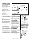
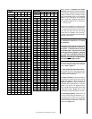
First Vent
Component
Align the dimple (four places)
with the opening of the locking
incline channel on appliance
collar. Twist vent component
clockwise to engage and seal.
Locking
Incline Channel
Dimple
45 degree starter elbow
Vent / 45 Degree Starter
Elbow Connection
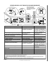
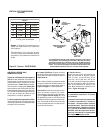
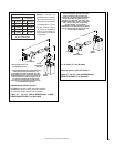
Figure 17
1 inch
(25.4 mm)
minimum
clearance to
combustibles
Support Straps
(Plumber’s tape)
8 feet (2.4 m)
Maximum
Blocking
Detail
Rigid Or Flex
Venting
Components May
Be Connected
Directly To The 45
Degree Collar.