


22
NOTE: DIAGRAMS & ILLUSTRATIONS NOT TO SCALE.
Step 4. FIELD WIRING
Caution: Label all wires prior to disconnec-
tion when servicing controls. Wiring errors
can cause improper and dangerous opera-
tion. Verify proper operation after servicing.
Refer to Section A for millivolt appliances and
Section B for electronic appliances. The gas
valve is set in place and pre-wired at the
factory on both models.
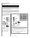
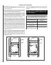
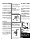
Note:
Secure Flex
vent must be attached to
Secure Flex
terminations only. DO NOT
substitute
Secure Vent
terminations or the
Secure Vent
adapter for
Secure Flex
compo-
nents. The collars of
Secure Flex
termina-
tions and adapters have a different circum-
ference than that used with the
Secure Vent
pipe. Additionally,
Secure Flex
components
have an extended length center tube for use
in attaching the flexible vent.
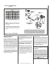
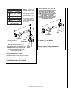
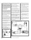
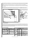
A. Millivolt Wiring
(See Figure 36 )
–
1. Appliance-mounted ON/OFF burner control
switch (rocker switch) is factory installed be-
hind the bottom panel. Optional wall-mounted
switch, thermostat, or one of the optional
remote control kits may also be used.
2. If wall-mounted ON/OFF control or thermo-
stat is selected mount it in a convenient loca-
tion on a wall near the fireplace.
3. Wire the control switch within the millivolt
control circuit using the 15 feet of 2 conductor
wire supplied with the unit.
Note: The supplied 15 feet of 2 conductor
wire has one end of each conductor con-
nected to the gas valve circuit and the other
end of each conductor placed loose inside
the bottom compartment.
Caution: Do Not connect the optional wall
switch to a 120V power supply.
Figure 36
Figure 37
4.If an optional control switch is installed, turn
the appliance-mounted ON/OFF burner con-
trol switch to the OFF position.
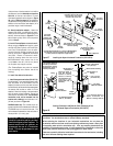
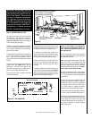
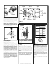
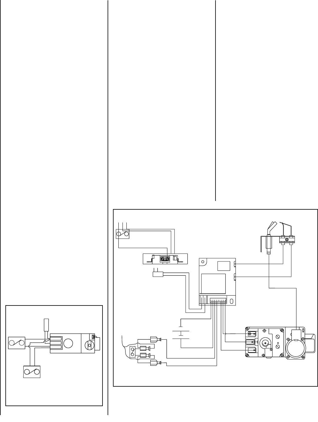
B. Electronic Wiring (See
Figure 37 )
–
Note: The electronic appliance must be con-
nected to the main power supply.
1. Route a 3-wire 120Vac 60Hz 1ph power
supply to the appliance junction box.
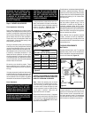
2. Remove the electrical inlet cover plate from
the side of the unit by removing the plate's
securing screws.
See Figure 11 on page 9.
3. Remove the cover plate's knockout and then
feed the power supply wire through the knock-
out opening and into the unit junction box.
4. Connect the black power supply wire to the
lower outlet's red pigtail lead and the white
power supply wire to the common terminal of
the outlet as shown in
Figure 37.
5. Connect the ground supply wire to the pigtail
lead attached to outlet's green ground screw.
6. Appliance-mounted ON/OFF burner control
switch (rocker switch) is factory installed be-
hind the bottom panel.
Optional wall-mounted switch, thermostat, or
one of the optional remote control kits may
also be used. The appliance mounted ON/OFF
switch needs to be relocated onto the optional
style view door, if used.
7. If wall-mounted ON/OFF control or thermo-
stat is to be used, mount it in a convenient
location on a wall near the fireplace.
8. If an optional control is to be used, wire it in
the low voltage circuit as shown in
Figure 37.
Note: The supplied 15 feet of 2 conductor wire
has one end of each conductor connected to the
gas valve circuit and the other end of each
conductor placed loose inside the bottom com-
partment.
9. If an optional control switch is installed,
turn the appliance-mounted ON/OFF burner
control switch to the OFF position.
10. After the wiring is complete, replace the
cover plate.
Note: No batteries to be installed in the
battery holder until a power outage, or if the
appliance is to be operated solely with two
(2) "D" batteries.
TP-TH
TP
TH
APPLIANCE- MOUNTED
ON/OFF SWITCH
BK/W(1)
BK/W(1)
WALL-MOUNTED ON/OFF SWITCH (OPTIONAL)
THERMOSTAT (OPTIONAL)
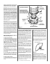
WIRING DIAGRAM MILLIVOLT GAS VALVES
THERMOPILE
GAS VALVE
JUNCTION BOX
W
GR
120 VAC
BK
TRANSFORMER 3V
INTERMITTENT ELECTRONIC WIRING DIAGRAM
BROWN
BROWN
BLACK
BATTERY BACK-UP
TO WALL
SWITCH OR
THERMOSTAT
BLACK (SENSOR)
BLACK (IGNITOR)
SPARK TO PILOT IGNITOR
IGNITOR MODULE
3V
RED
BK
W
GR
PILOT
IN
OUT
VENT
LO
HI
TH
TP
TH
TP
IN
ORANGE (THTP)
BLACK (TP)
GREEN (TH)