


NOTE: DIAGRAMS & ILLUSTRATIONS NOT TO SCALE.
23
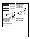
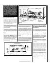
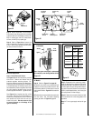
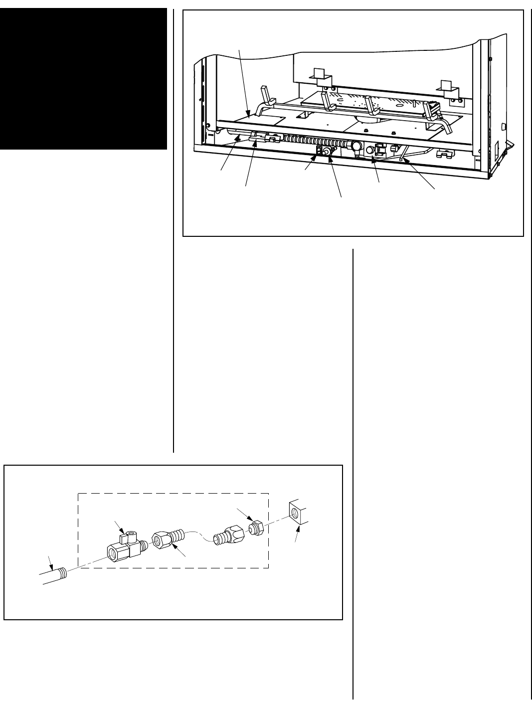
Figure 39
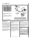
Step 5. CONNECTING GAS LINE
All codes require a shut-off valve mounted in
the supply line. The orientation of the shut-
off valve should face the front, as shown in
Figure 39
.
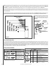
Figure 38
illustrates the method
for connecting the gas supply.
The flex-line method is acceptable in the U.S.,
however, Canadian requirements vary depend-
ing on locality. Installation must be in compli-
ance with local codes.
These appliances are equipped with a gas flex
line for use in connecting the unit to the gas
line. A gas flex line is provided to aid in
attaching the direct vent appliance to the gas
supply.
The gas flex line can only be used where local
codes permit. See
Figure 38
for flex line
description. The flex line is rated for both
natural and propane gas. A manual shut off
valve is also provided with the flex line.
The gas control valve is located in the lower
control compartment.
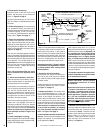
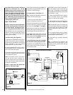
IMPORTANT: Ground supply lead must
be connected to the wire attached to the
green ground screw located on the out-
let box. See
Figure 37
. Failure to do so
will result in a potential safety hazard.
The appliance must be electrically
grounded in accordance with local codes
or, in the absence of local codes, the
National Electrical Code, ANSI/NFPA 70-
(latest edition). (In Canada, the current
CSA C22-1 Canadian Electrical Code.)
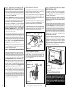
These appliances come from the factory with
the gas line access plate removed to provide
full access to the end of the gas flex line.
As designed, the glass door needs to be
opened to access the open gas access area.
Route a hard pipe from the left to a spot
directly below the access plate opening.
Bring the shutoff valve on the end of the flex
line over to the hard pipe and tighten with
wrenches from above through the firebox
opening.
If required, access the valve by removing the
lower control compartment panel (
see Figure
39
) by lifting and pulling the panel forward.
The millivolt and electronic control valve has a
3/8" (10 mm) NPT thread inlet port.
Secure all joints tightly using appropriate
tools and sealing compounds (ensure pro-
pane resistant compounds are used in pro-
pane applications).
Turn on gas supply and test for gas leaks,
using a gas leak test solution (also referred to
as bubble leak solution).
Note: Using a soapy water solution (50% dish
soap, 50% water) is an effective leak test
solution but it is not recommended, because
the soap residue that is left on the pipes/
fittings can result in corrosion over time. Never
use an open flame to check for leaks.
A. Light the appliance (refer to the lighting
instructions label in the control compartment
or in the Homeowner's Care and Operation
Instructions).
B. Brush all joints and connections with the
gas leak test solution to check for leaks. If
bubbles are formed, or gas odor is detected,
turn the gas control knob to the “OFF” posi-
tion. Either tighten or refasten the leaking
connection and retest as described above.
C. When the gas lines are tested and leak free,
be sure to rinse off the leak testing solution.
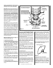
D. When the gas lines are tested and leak free,
observe the individual tongues of flame on the
burner. Make sure all ports are open and
producing flame evenly across the burner. If
any ports are blocked, or partially blocked,
clean out the ports.
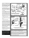
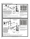
Figure 38 -
GAS CONNECTION
Gas
Stub
1/2" x 3/8" Flare
Shut-Off Valve
3/8" Flex Tubing
3/8" NPT x 3/8"
Flare Fitting
Gas
Valve
Flex Line Connector
Piezo Ignitor
Gas Valve
Gas Line Access Plate Not Installed
At The Factory. It Is Included In
The Installation Instruction Bag.
ON/OFF
Switch
Gas
Supply
Line
Shut-Off Valve
(Orientation
As Shown)
Air Shutter
Adjustment Arm