


24
NOTE: DIAGRAMS & ILLUSTRATIONS NOT TO SCALE.
Figure 40
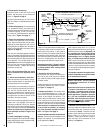
Door
Assembly
Gas Line Access Panel
Bottom Panel
Burner
Assembly
Figure 42
-
Figure 41
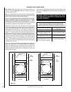
INSTALLING THE GLASS DOOR
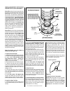
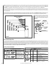
ELECTRONIC
Pilot
Hood
Sensor
Ignitor
MILLIVOLT
Thermocouple
Hood Ignitor Rod
3/8
" Min
(9 mm)
Thermopile
Pilot
Nozzels
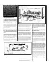
Step 6. INSTALLING THE LOGS, GLOW-
ING EMBERS AND VOLCANIC STONES
Step 7. CHECKING APPLIANCE OPERATION
With gas line installed run initial system check-
out before closing up the front of the unit.
Follow the pilot lighting instructions provided
in the Homeowner's Care and Operation In-
structions. For piezo ignitor location see
Fig-
ure 39 on page 23
(millivolt appliances only).
Note: Lighting Instructions are also found on
the literature tag tied to the gas piping next to
the gas valve. To access the tag, open the
lower control compartment door (Figure 39 on
page 23 ) by pulling the panel forward.
When first lighting the appliance, it will take
a few minutes for the line to purge itself of
air. Once purging is complete, the pilot and
burner will light and operate as indicated in
the instruction manual. Subsequent lighting
of the appliance will not require such purg-
ing. Inspect the pilot flame (remove logs, if
necessary, handling carefully).
Proper log and twig placement is critical to
encourage outstanding flame appearance and
prevent sooting. These fires are designed to
provide a rich orange/red glow on the logs.
Ensure the bottom of the rear log is fully seated
and pulled as far forward as the pins will al-
low. Refer to the Log Set Placement
Supplement for detailed instructions.
Note: Log setup is by design asymmetric. The
fire is intentionally positioned off center to
provide a natural fire look.
The logs are packaged in a carton located
within the firebox. One plastic bag of glowing
embers and volcanic stones are located in the
bottom compartment. Refer to the Log Set
Placement Supplement for detailed place-
ment instructions for the logs, glowing em-
bers and volcanic stones.
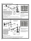
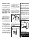
Remove the gas line access plate and gasket
from the provided plastic bag and install them
over the opening, using the provided screws
(4) as shown in
Figure 39
.
Refer to
Figure 43
and loosen the set screw
for the venturi air shutter. Manually actuate
the air shutter through several cycles. Set the
air shutter to 3/32" before placing the logs.
Millivolt Appliance Checkout
The pilot flame should be steady, not lifting or
floating. Flame should be blue in color with
traces of orange at the outer edge.
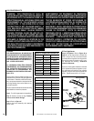
The top 3/8" (10 mm) at the pilot generator
(thermopile) and the top 1/8" min (tip) of the
quick drop out thermocouple should be en-
gulfed in the pilot flame.
The flame should project 1" (25 mm) beyond
the hood at all three ports
(Figure 40 ).
Re-
place logs if removed for pilot inspection.
To light the burner; turn “ON” the remote wall
switch and rotate the gas valve control knob
counterclockwise to the “ON” position (“ON”
will be at the bottom side of the valve).
WARNING: HANDLE THIS GLASS WITH
EXTREME CARE! THE GLASS PANEL IS
SUSCEPTIBLE TO DAMAGE — DO NOT
SCRATCH WHILE HANDLING OR WHILE
RE-INSTALLING THE GLASS DOOR
FRAME.
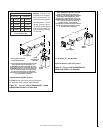
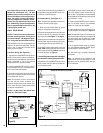
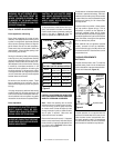
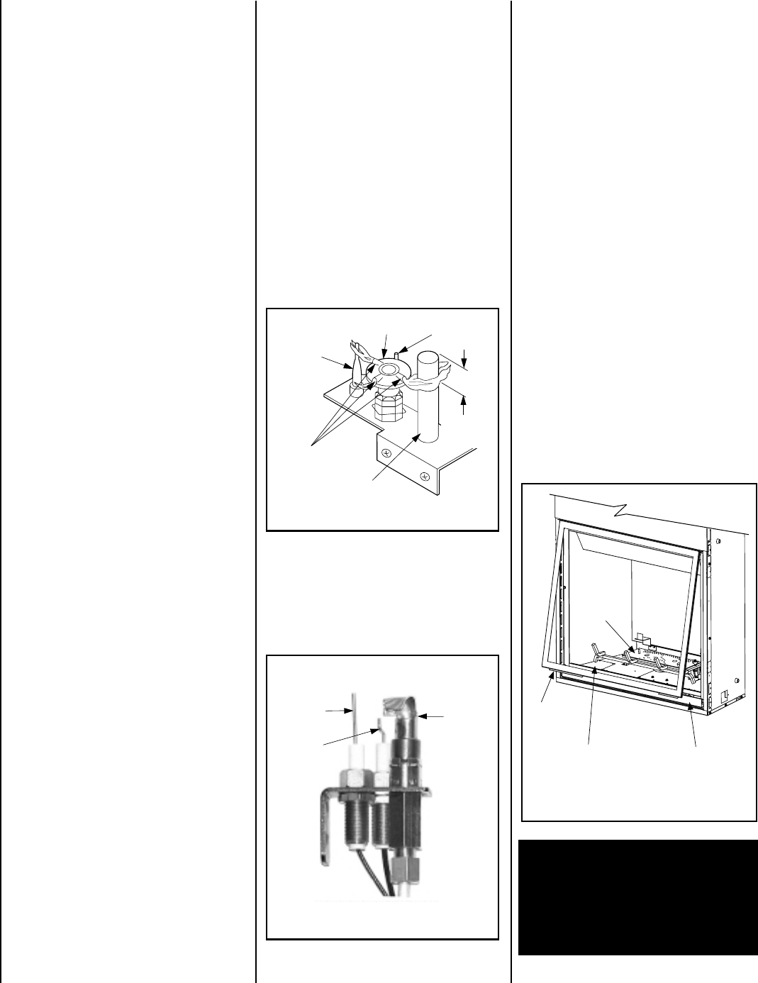
Step 8. INSTALLING THE GLASS DOOR
AND OPTIONAL HOOD
To access the glass door securing latches,
first open the lower control compartment
door (
Figure 42
) by lifting and pulling the
bottom panel forward.
Retrieve the glass door. Visually inspect the
gasket on the backside of the frame. Gasket
surface must be clean, free of irregularities and
seated firmly.
Position the door in front of the firebox opening
with the bottom of the door held away from the
fireplace
(Figure 42 )
. Hook the top flange of
the door frame over the top of the firebox frame.
Let the bottom of the door frame swing gently
in towards the fireplace ensuring that the gas-
ket seats evenly as the door frame draws shut.
Fasten the two latches located underneath the
firebox floor to the door's vee-flange. Close
both the latches securely.
If desired, install the optional hood. Note the
location of the three clips inside the top air
channel above the door. The clips are equally
spaced on the top surface of the air channel
opening. Use a screwdriver to open the clips
slightly if needed. Engage the back edge of the
eyebrow into the clips to secure.
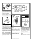
Electronic Appliance Checkout
To light the burner, turn ‘ON’ the unit mounted
On/Off switch or the optional remote wall
switch. Ensure the ignitor lights the pilot. The
pilot flame should engulf the flame rod as
shown in
Figure 41
.