


NOTE: DIAGRAMS & ILLUSTRATIONS NOT TO SCALE.
29
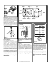
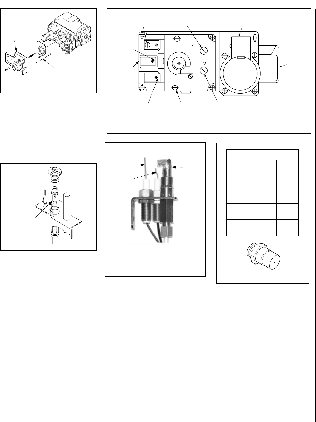
Pressure
Regulator
Remove
These
Components
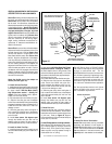
Pilot
Orifice
Figure 51
Figure 50
Figure 52
Figure 49
Figure 48
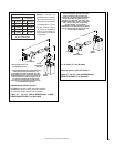
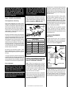
Note: If the ignitor is damaged, a replacement
kit is available, order Catalog Number 87L54.
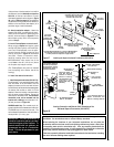
Electronic Appliances
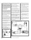
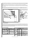
Step 7. Dexen Electronic Valves -
See
Figure 50
and the instructions provided
with the kit. Remove and discard the two
pressure regulator mounting screws. Re-
move the pressure regulator and diaphragm.
Discard all removed components. Ensure the
provided diaphragm is installed properly onto
the replacement pressure regulator and install
the new pressure regulator using the new
screws supplied with the kit. Tighten screws.
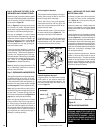
See
Figure 51
and replace the pilot orifice
as follows: Remove pilot hood assembly to
access the phillipped pilot orifice. Remove
and replace the orifice with the one pro-
vided with the kit. Exercise extreme care
to prevent damage to or breakage of the
ignitor assembly.
Step 9. Reassemble the remaining compo-
nents by reversing the procedures outlined in
the preceding steps. Use pipe joint compound
or Teflon tape on all pipe fittings before install-
ing (ensure propane resistant compounds are
used in propane applications, do not use pipe
joint compounds on flare fittings).
Step 10. Attach the conversion label provided
in the conversion kit to the rating plate on the
appliance.
Step 11. Turn on gas supply and test for gas
leaks.
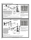
All Models
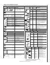
Step 8. (Refer to
Figure 47 on page 28
)
A. Remove the orifice from the manifold and
replace it with the one provided in the kit. See
the following table for orifice sizes for natural
and propane models
. Figure 52
illustrates the
orifice.
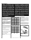
B. Retrieve the burner and slide the venturi tube
over the orifice. Set the shutter adjusting
opening as shown in
Figure 43
, page 25.
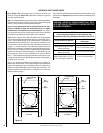
Step 5. Attach manometer to the manifold
side pressure test fitting and verify manifold
pressure reads 3.5 inches water column (0.87
kPa) for natural gas, and 10.0 inches water
column (2.49 kPa) for propane gas.
Step 6. Refer to
Figure 49
and remove the
pilot hood assembly to access the hexed pilot
orifice. Remove and replace the orifice with
the one provided with the kit.
ELECTRONIC
Pilot
Hood
Sensor
Ignitor
.oNledoM
ezisecifirO
larutaNenaporP
03-VDLPM"070.0
16#
)"930.0(
53-VDLPM
54#
)"280.0(
"840.0
04-VDLPM
14#
)"640.0(
45#
)"550.0(
54-VDLPM
04#
)"890.0(
35#
)"595.0(
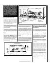
Pilot Stage
Terminal
Pressure-Tap
(Inlet)
Pilot Gas
Outlet
Supply
Gas Inlet
Pressure-Tap
(Manifold)
Burner Stage
Terminal
Ground
(TP)
PILOT
OUT
VENT
LO
TH
TP
TH
TP
HI
IN
IN
Gas Outlet
To Burner
Regulator
Mounting Screw