


NOTE: DIAGRAMS & ILLUSTRATIONS NOT TO SCALE.
25
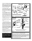
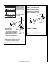
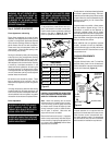
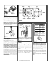
Figure 43
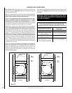
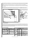
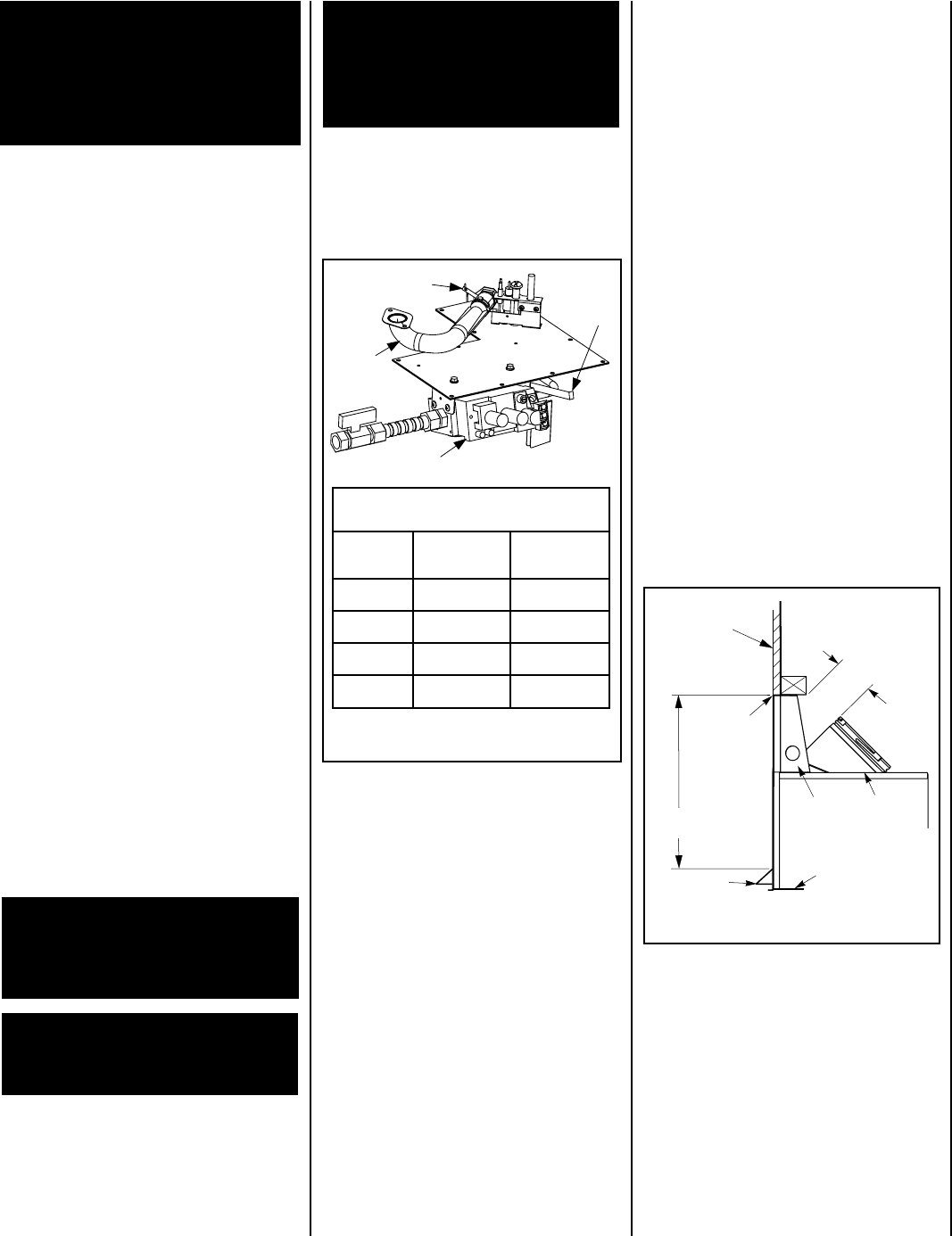
Figure 44
Burner Adjustment
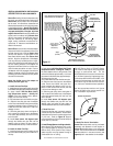
Step 9. BURNER ADJUSTMENTS
Flame Appearance and sooting
Proper flame appearance is a matter of taste.
Generally, most people prefer the warm glow of
a yellow to orange flame. Appliances operated
with air shutter openings that are too large will
exhibit flames that are blue and transparent.
These weak, blue and transparent flames are
termed anemic. If the air shutter opening is too
small sooting may develop.
Sooting is indicated by black puffs developing
at the tips of very long orange flames. Sooting
results in black deposits forming on the logs,
appliance inside surfaces and on exterior sur-
faces adjacent to the vent termination. Sooting
is caused by incomplete combustion in the
flames and lack of combustion air entering the
air shutter opening. To achieve a warm yellow
to orange flame with an orange body that does
not soot, the shutter opening must be adjusted
between these two extremes.
No smoke or soot should be present. These
logs are designed to be involved in the fire.
Flames will impinge the top tips of the right and
left logs.
If the logs are properly positioned and sooting
conditions exist, the air shutter opening on the
main burner tube should be adjusted. Normally,
the more offsets in the vent system, the greater
the need for the air shutter to be opened further.
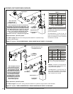
To adjust the flame, rotate the lever arm up or
down (rod located in the lower control area).
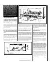
Position the air shutter to the factory setting as
shown in the table in
Figure 43
. Allow the
burner to operate for at least 20 minutes.
WARNING: AIR SHUTTER ADJUST-
MENT SHOULD ONLY BE PER-
FORMED BY A QUALIFIED PROFES-
SIONAL SERVICE TECHNICIAN.
IMPORTANT: ENSURE THAT THE FRONT
GLASS PANEL IS IN PLACE AND SEALED
DURING ADJUSTMENT.
CAUTION: THE AIR SHUTTER DOOR
AND NEARBY APPLIANCE SURFACES
ARE HOT. EXERCISE CAUTION TO
AVOID INJURY WHILE ADJUSTING
FLAME APPEARANCE.
FINISHING REQUIREMENTS
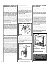
Wall Details
Complete finished interior wall. To install the
appliance facing flush with the finished wall,
position framework to accommodate the thick-
ness of the finished wall (
Figure 44
)
CAUTION: DO NOT BEND THE AIR SHUTTER
ROD. MAKE SURE THE AIR SHUTTER MOVES
WHEN THE LEVER ARM IS OPERATED.
Note: When first operating the air shutter
adjustment lever arm observe the air shutter.
If it is not moving, open the glass, ensure the
air shutter screw is loose and adjust by hand
through a couple of cycles, to break the adhe-
sion of paint, if required. Close door and
adjust with the lever as needed.
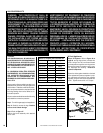
Observe the flame continuously. If it appears
weak or sooty as previously described, adjust
the air shutter by rotating the adjustment arm
up or down (
refer to Figure 39
) until the flame
appearance is as desired.
The adjustment rod and associated adjustable
air shutter is patented technology. Flame ad-
justments can be made quickly and accurately
to taste without the need of disassembling the
appliance and waiting for 30 minutes after
each adjustment.
Propane models may exhibit a flame pattern
that may candle or appear stringy. If this is
problematic or persists as the appliance is
continually operated, adjust the air shutter
closed as described in the previous paragraphs.
Operate the appliance for a period of time as the
effect diminishes, ensuring that the appliance
does not develop sooty flames.
When satisfied that the appliance operates
properly, proceed to finish the installation.
Leave the control knob in the ON position and
the remote switch OFF. Close the lower control
compartment door.
RENRUBNIAM
GNITTESGNINEPORETTUHSYROTCAF
sledoM
saGlarutaN
)mm(sehcni
saGenaporP
)mm(sehcni
03VDLPM)83.2(23/3)67.4(61/3
53VDLPM)6.1(61/1)53.6(4/1
04VDLPM)53.6(4/1)5.9(8/3
54VDLPM)53.6(4/1)7.21(2/1
Venturi
Air Shutter Rod
Valve
Air
Adjustment
Arm
A hearth extension is not required with this
appliance. If a hearth extension is used, do not
block the lower control compartment door.
Any hearth extension used is for appearance
only and does not have to conform to standard
hearth extension installation requirements.
Combustible
Finished Wall
Materials
This Area Must
Remain Clear
of Combustible
Materials
Top of
Appliance
3-1/2" Min
(89 mm)
Spacer
Combustible
materials not
allowed
below this
point on
the face of the
appliance.
Optional Hood
Top of Door Frame
10" Min
(254 mm)
WARNING: DO NOT OPERATE APPLI-
ANCE WITH THE GLASS FRONT RE-
MOVED, CRACKED OR BROKEN. RE-
PLACEMENT OF THE GLASS SHOULD
BE DONE BY A LICENSED OR QUALIFIED
SERVICE TECHNICIAN.