


16
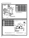
NOTE: DIAGRAMS & ILLUSTRATIONS NOT TO SCALE.
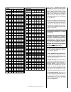
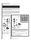
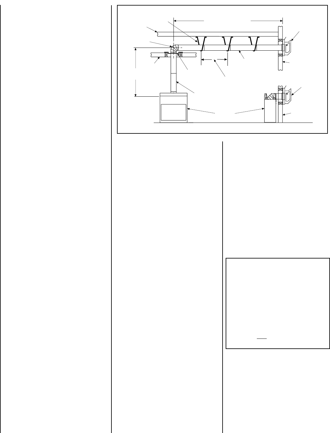
Vertical
Rise
SV4.5E90
Elbow
Horizontal / Inclined Run
SV4.5 HT-2
Termination
Firestop/Spacer
SV4.5L6/12/24/36/48
Vent Sections
Support Bracket Spacing
Every 5 ft (1.52 m)
See Figure 17 on page 12 for
vertical vent section support.
SV4.5 HT-2
Termination
Support
Brackets
Building
Support
Framing
Ceiling
Fireplace
Exterior
Wall
Exterior
Wall
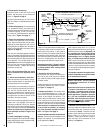
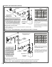
TYPICAL HORIZONTAL VENT INSTALLATION
Figure 26
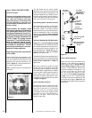
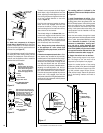
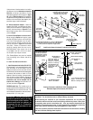
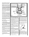
Push the vent component against the elbow
until it fully engages, then twist the component
clockwise, running the dimples down and along
the incline channels until they seat at the end
of the channels. The unitized design of the
Secure Vent components will engage and seal
both the inner and outer pipe elements with
the same procedure. Sealant and securing
screws are not required.
Note: A 90 or 45 degree elbow may not be
directly attached to the appliance elbow
collar.
G. Attach vent components to each other -
Other vent sections may be added to the pre-
viously installed section in accordance with
the requirements of the vent tables.
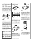
To add another vent component to a length of
vent run, align the dimpled end of the compo-
nent over the inclined channel end of the
previously installed section, adjusting the ra-
dial alignment until the four locking dimples
are aligned with the inlets of the four incline
channels of the previous section.
Push the vent component against the previous
section until it fully engages, then twist the
component clockwise running the dimples
down and along the incline channels until they
seat at the end of the channels.This seating
position is indicated by the alignment of the
arrow and dimple as shown in
Figure 16 on
page 12.
H. Install firestop/spacer at ceiling -
When using Secure Vent, use SV4.5VF firestop/
spacer at ceiling joists; when using Secure Flex,
use SF4.5VF firestop/spacer.
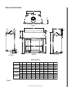
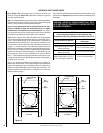
D. Frame exterior wall opening -
Locate the center of the vent outlet on the
exterior wall according to the dimensions
shown in
Figure 9
on page 8.
Cut and/or frame an opening, 10-1/2" x 12-1/8"
(267 mm x 308mm) inside dimensions, about
this center.
E. Frame ceiling opening - If the vertical route
is to penetrate a ceiling, use plumb line to
locate the center above the appliance. Cut and/
or frame an opening, 10-1/2" x 10-1/2" (267
mm x 267 mm) inside dimensions, about this
center (refer to
Figure 14
on page 11 ).
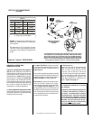
Install support straps every 5 ft. (1.52 m)
along horizontal/inclined vent runs using con-
ventional plumber’s tape. See
Figure 26
, it is
very important that the horizontal/inclined
run be maintained in a straight (no dips) and
recommended to be in a slightly elevated
plane, in a direction away from the fireplace
of 1/4" rise per foot (20 mm per meter) which
is ideal, though rise per foot run ratios that are
smaller are acceptable all the way down to at or
near level
.
Use a carpenter’s level to measure
from a constant surface and adjust the support
straps as necessary.
It is important to maintain the required clear-
ances to combustibles at the top and bottom
for all horizontal/inclined runs.
If there is living space above the ceiling level,
the firestop/ spacer must be installed on the
bottom side of the ceiling.
If attic space is
above the ceiling, the firestop/ spacer must be
installed on the top side of the joist. Route the
vent sections through the framed opening and
secure the firestop/spacer with 8d nails or
other appropriate fasteners at each corner.
Remember to maintain 1" (25 mm) clearance
to combustibles, framing members, and attic
or ceiling insulation when running vertical
chimney sections.
I. Support the vertical run sections -
On the vertical run, support the venting sys-
tem every 8 feet (2.4m) above the fireplace
vent outlet with field provided support straps
(Plumber's tape).
Attach the straps to the vent pipe and secure to
the framing members with nails or screws.
See
Figure 17 on page 12.
J. Change vent direction - At transition from
or to a horizontal/inclined run, install the
SV4.5E45 and SV4.5E90 elbows in the same
manner as the straight vent sections. The
elbows feature a twist section to allow them
to be routed about the center axis of their
initial collar section to align with the required
direction of the next vent run element. Twist
elbow sections in a clockwise direction only
so as to avoid the possiblity of unlocking
any of the previously connected vent sec-
tions. See
Figure 18 on page 13
.
K. Continue installation of horizontal/inclined
sections - Continue with the installation of the
straight vent sections in horizontal/inclined
run as described in Step F.
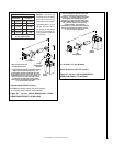
F. Attach vent components to starter elbow -
To attach a vent component to the the starter
elbow, align the dimpled end over the collar,
adjusting the radial alignment until the four
locking dimples are aligned with the inlets of
the four incline channels on the collar (
refer to
Figure 15
on page 12).
L. Assemble vent run to exterior wall - If not
previously measured, locate the center of the
vent at the exterior wall. Prepare an opening
as described in Step D. Assemble the vent
system to point where the terminus of the last
section is within 7 in. (178 mm) to 11-1/4 in.
(286 mm) inboard of the exterior surface to
which the SV4.5 HT-2 termination is to be
attached, see
Figure 28
.
Maintain a minimum 1" (25 mm) clearance
to combustible materials for all vertical
vent elements.
Clearances for horizontal vent elements are
1" (25 mm) at the sides and 1" (25 mm) on
the bottom. Clearances above horizontal
vent elements are 3" (76 mm) for all models
and all applications.
Exception: Clearance
is 5" (127 mm) for MPLDV35, MPLDV40 &
MPLDV45, when the center line of the hori-
zontal run is less than 48" (1219 mm) above
the fireplace top wrapper surface.