


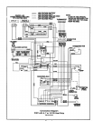
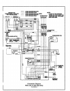
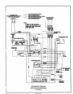

Usewiringwithatemperaturelimitation of 75 =C mini-
mum. Run the 208 or 230 volt, 60 hertz electric power
supply through a fused disconnect switch to the control
box of the unitand connect as shown in the wiring dia-
gram located on the inside of the control access panel.
The unit must be electrically grounded in accordance with
local codes or, in the absence of local codes, with the
National Electrical Code ANSI/NFPA No. 70 (latest edition)
or CSA C22.2 Part 1 (latest edition).
Power supply to the unit must be NEC Class 1 and must
comply with all applicable codes. A fused disconnect
switch should be field provided for the unit. The switch
must be separate from all other circuits. If any of the wire
supplied with the unit must be replaced, replacement wire
must be of the type shown on the wiring diagram.
Electrical wiring must be sized to minimum circuit
ampacity marked on the unit. Use copper conductors
only. Each unit must be wired with a separate branch
circuit and be properly fused.
OPERATION
Sequence of Operation
Cooling
When the thermostat is in the cooling mode, the O circuit
is powered which energizes the reversing valve. Upon
cooling demand, the thermostat closes circuit R toY and
G. Closing R to Y closes the unit contactor, starting the
compressor and outdoor fan. The thermostat automati-
cally closes R to G circuit which also brings on the indoor
blower at the same time. Upon satisfying cooling demand,
the thermostat will open the above circuits and open the
main contactor, stopping the compressor and outdoor fan.
If the unit is equipped with a time delay, the blower will
continue to operate for 90 seconds which improves
system efficiency.
Heating
Upon heating demand, the thermostat closes circuit R to
Y, which closes the unit contactor, starting the compressor
and outdoor fan. The reversing valve is not energized in
the heating mode. -The thermostat again automatically
brings on the indoor fan at the same time. The second
stage of the thermostat closes circuit R to W, which closes
the unit sequencers, bringing the auxiliary electric heat on.
Upon satisfying heating demand, the thermostat opens
the above circuits and stops unit operation.
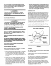
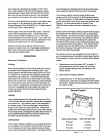
Defrost Cycle
Ifthe outdoor ambient conditions are such that frost forms
on the outdoor coil, the defrost control monitors the need
for and initiates and terminates defrost cycles as neces-
sary to maintain system performance. The defrost control
is time/temperature initiated and temperature terminated
with a maximum defrost time (time-out) of 10 minutes.
Time between defrost cycles is preset at 60ominute
intervals at the factory, but can be field adjusted between
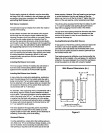
30, 60 or 90 minutes. To field adjust time between defrost
cycles, place defrost time plug in the proper position (see
Figure 3). For best performance in Region IV, the
PWC243 defrost interval should be adjusted to 30 min-
utes.
Defrost control will initiate a defrost cycle ifthe time period
has elapsed and the defrost sensor sees a temperature
below freezing. At the start of a defrost cycle, the defrost
control will energize the reversing valve solenoid, shifting
the reversing valve and de-energizing the outdoor fan.
The defrost relay will also close, energizing auxiliary heat
for increased comfort during defrost. The unit will remain
in defrost mode until the defrost sensor has determined
that the frost has been removed from the coil or a 10-
minute time period has elapsed.
The defrost control is also equipped with a setof pins to
aid in troubleshooting of the defrost system (see Figure 3).
The following is a brief outline of the testing of the defrost
system.
. Defrost sensor must be closed, 32°F or below. If
temperatures are such that switch will not close,
jumper between defrost sensor terminals on the
defrost control,
2. Start system in heating operation.
.
Jumper test pins, A 1/4" quick connect terminal
crimped onto a solid wire or brazing rod works well for
test jumper. Closing test pins speeds up time interval
by a factor of 256.
Defrost
TestPins.,,,=i
Defro=/
TimePlug
Defrost Control
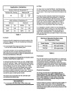
Defrost Control Setting Defrost Test Cycle Time
30 minutes 7 seconds
60 minutes 14 seconds
90 minutes 21 seconds
FinHr