


I PA,,NO.I ,, g,o094I DATEI '-fS-g'I SUPERSEDESI ,EW I PAGE3OF,O
LOCATION
Thedesign is certifiedfor through-the-wallinstallationonly.The interiorportionsoftheunit may besurroundedbya
cJosetwith clearancesto combustiblematerial heldto O" at sides, 0" topand 0" frontof the plenum.
Thegrille sideofthe unit maybe flush with or extendbeyondthe faceof theexteriorwall,but shouldnotberecessed
more than two (2) inchesfrom the face of thebuilding andshould notbeobstructed with trees, landscapematerials,
or building structure.
Thereis no minimum clearancerequired on locatinga unit toan interior cornerof a building. If the unit istobe enclos-
ed, provisionsshouldbe madeallowing accessto the indoorside of the unit tot changingfilters andfor inspection. At
least 33" ol unobstructed space should be provided in fronl of the indoorside, whether enclosed or not, to permit
removalof the cooling chassis shouJdrepairs or inspection be required,
If this unit is installed in a residential garage it must be located or protectedto avoidphysical damage by vehicles.
This unit must be installed so that no electrical componentsare exposedtowater.
INSTALLATION
CAUTION:THESLEEVEIS NOTINTENDEDAS THESOLESUPPORTFORTHEUNIT. ANADDITIONALSUPPORTMUST
BEPROVIDEDNEARTHE RETURNOPENINGONTHE UNIT FORADEQUATESUPPORT.THE USE OF VIBRATION
ISOLATIONMATERIALBETWEENTHE UNIT AND THESUPPORTIS RECOMMENDED.
CAUTION:THIS UNITMUST BEINSTALLEOLEVELFORPROPERDRAINAGEOFTHECHASSISBASEPANAND UNIT
DRAINPAN.
WITHOUTWALLSLEEVE
Measurethe sizeofthe unit andprovideanopeningin anoutsidewallthatwillaccepttheunit. Localordinancesmay
require a steel lintelto supportthe wall abovethe opening.This opening must be square in all corners.
Positionthe unitsothat the gritles on the outsideface of theunit areflush or extendbeyondthe faceof the exterior
wall, but notrecessedmore than two (2) inchesfrom theface ofthe building. PROVIDEA SUPPORTUNDERTHEUNIT
INSIDETHE BUILDING.Makesure that theinsidesupport doesnot block thereturn air. The unit shouldbe installed
level.
Sealthe spacebetweenthe unitandthe buildingopening usinga non-hardeningcaulkingcompound.Thesealmust
be weather-tight to prevententrance ol moisture andwaterinto thebuilding. Make surethe drainholes in thebase
are not plugged with caulking.
WITH WALL SLEEVE
Seethe installationinstructionspacked with the wall sleeveto assembleandamountin a wall. Make surethat the
gaskets attachedtothe sleeveare not damaged. Assurethat the unitis completelyseatedagainst the gaskets onthe
wall sleeve.
Sealspace betweenwail sleeveand building opening using non-hardeningcaulkingcompound.This seal must be
watertight,
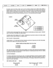
CONDENSATEDRAIN
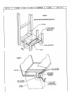
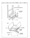
Install theplastic drain tube(furnished) over the5/8" O.D. fitting weldedtothe condensatepan. Connectotherend
of the drain tubetotrapped drain line (See Figure 2). Theplastic drain connectionto thechassisbaseis provided so
that it may be disconnected from the permanent drain tubingin thebaseof unitin theevent it becomesnecessaryto
remove the chassis assembly.
The drain lineshouldpitch gradually downward at least 1" per 10 loot of horizontal run to the open drain.
Be certainthat theplaslic drain tubinghas freedrainage and is not crimpedor flattened at any bend,