


If the unit is installed in a residential garage, it must be
located or protected to avoid physical damage by vehicles.
The unit must be installed so that no electrical compo-
nents are exposed to water.
I
[A CAUT,ON]
This unit must be installed level to allow for
proper drainage of the chassis base pan and
unit drain pan.
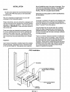
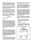
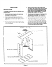
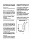
Installing With a Wall Sleeve
[ _, CAUTION l
The sleeve is not intended as the sole support
for the unit. An additional support must be
provided near the return opening on the unit
for adequate support. The use of vibration
isolation material between the unit and the
support is recommended.
Refer to the installation instructions packed with the wall
sleeve and Figure 1 for guidance in assembly and mount-
ing using a wall sleeve.
Make sure the gaskets attached to the sleeve are not
damaged.
Seal the space between the wall sleeve and-the building
opening with non-hardening caulking compound. The seal
must be weathertight to prevent entrance of moisture and
water into the building.
Assure that the unit is completely seated against the
gaskets on the wall sleeve.
Installing Without a Wall Sleeve
Refer to the following directions and Figure I for guidance
in installing the unit without a wall sleeve:
.
Measure the size of the unit and provide an opening in
an outside wall that will accept the unit. Local ordi-
nances may require a steel lintel to support the wall
above the opening. The opening must be square in all
4 corners.
,
Position the unit so that the grilles on the outside face
of the unit are flush or extend beyond the face of the
exterior wall, but not recessed more than 2" from the
face of the building. Provide a support under the
unit, inside the building. Make sure that the inside
support does not block the return air. The unit should
be installed level
.
Seal the space between the unit and building opening
using a non-hardening caulking compound. The seal
mustbe weathertight to prevent entrance of moisture
and water into the building. Make sure the drain holes
in the base are not plugged with caulking,
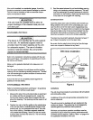
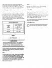
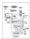
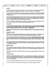
Condensate Drain
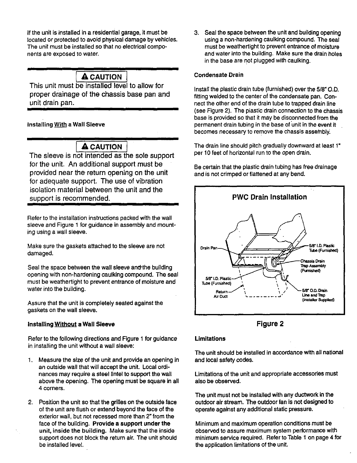
Install the plastic drain tube (furnished) over the 5/8" O.D.
fitting welded to the center ofthe condensate pan. Con-
nect the other end of the drain tube to trapped drain line
(see Figure 2). The plastic drain connection to the chassis
base is provided so that it may be disconnected from the
permanent drain tubing in the base of unitin the event it
becomes necessary to remove the chassis assetnbly.
The drain line should pitch gradually downward at least 1"
per 10 feet of horizontal run to the open drain.
Be certain that the plastic drain tubing has free drainage
and is not crimped or flattened at any bend.
PWC Drain Installation
Drain Pan_
Figure 2
Limitations
The unitshould be installed in accordance with all national
and local safety codes.
Limitations of the unit and appropriate accessories must
also be observed.
The unitmust not be installed with any ductwork in the
outdoor air stream. The outdoor fan is not designed to
operate against any additional static pressure.
Minimum and maximum operation conditions must be
observed to assure maximum system performance with
minimum service required. Refer to Table 1 on page 4 for
the application limitations of the unit.