


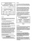
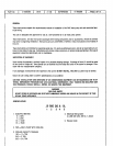
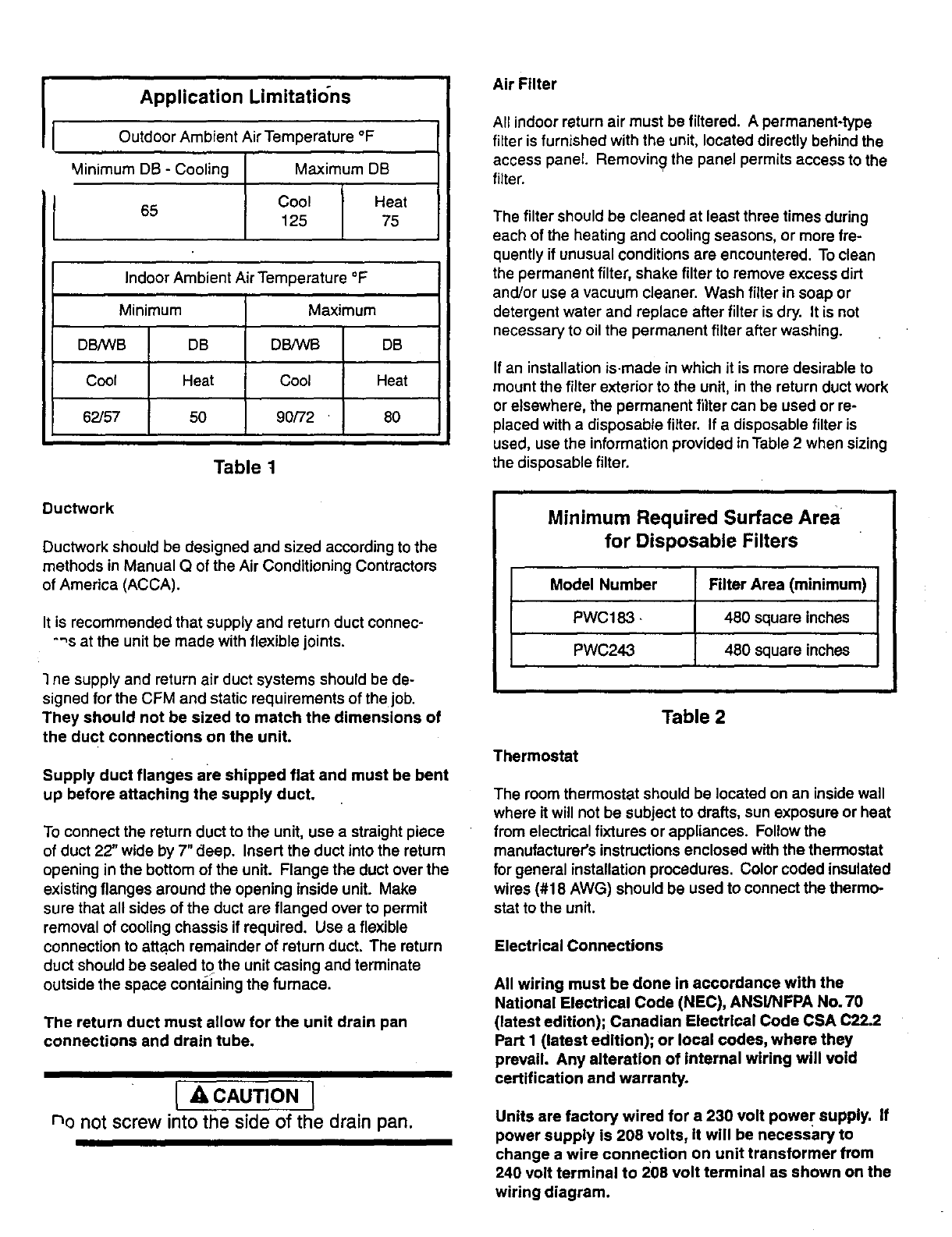
Application Limitations AirFilter
Outdoor Ambient Air Temperature °F
Minimum DB - Cooling Maximum DB
Cool Heat
65
125 75
Indoor Ambient Air Temperature °F I
Minimum Maximum
DB/WB DB DB,_VB DB
Cool Heat Cool Heat
62/57 50 90/72 80
Table t
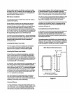
Ductwork
Ductwork should be designed and sized according to the
methods in Manual Q of the Air Conditioning Contractors
of America (ACCA).
It is recommended that supply and return duct connec-
-'_s at the unit be made with flexible joints.
1ne supply and return air duct systems should be de-
signed for the CFM and static requirements of the job.
They should not be sized to match the dimensions of
the duct connections on the unit.
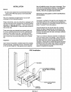
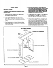
Supply duct flanges are shipped flat and must be bent
up before attaching the supply duct.
To connect the return duct to the unit, use a straight piece
of duct 22" wide by 7" deep. Insert the duct into the return
opening in the bottom of the unit. Flange the duct over the
existing flanges around the opening inside unit. Make
sure that all sides of the duct are flanged over to permit
removal of cooling chassis if required. Use a flexible
connection to attach remainder of return duct. The return
duct should be sealed to the unit casing and terminate
outside the space contai_ningthe furnace.
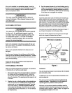
The return duct must allow for the unit drain pan
connections and drain tube.
[ ACAUTION J
no not screw into the side of the drain pan.
All indoor return air must be filtered. A permanent-type
filter is furnished with the unit, located directly behind the
access panel. Removing the panel permits access to the
filter.
The filter should be cleaned at least three times during
each of the heating and cooling seasons, or more fre-
quently if unusual conditions are encountered. To clean
the permanent filter, shake filter to remove excess dirt
and/or use a vacuum cleaner. Wash filter in soap or
detergent water and replace after filter is dry. It is not
necessary to oil the permanent filter after washing.
If an installation is.made in which it is more desirable to
mount the filter exterior to the unit, in the return duct work
or elsewhere, the permanent filter can be used or re-
placed with a disposable filter. If a disposable filter is
used, use the information provided in Table 2 when sizing
the disposable filter.
Minimum Required Surface Area
for Disposable Filters
Model Number Filter Area (minimum)
PWC183 - 480 square inches
PWC24,3 480 square inches
Table 2
Thermostat
The room thermostat should be located on an inside wall
where it will not be subject to drafts, sun exposure or heat
from electrical fixtures or appliances. Follow the
manufacturer's instructions enclosed with the thermostat
for general installation procedures. Color coded insulated
wires (#18 AWG) should be used to connect the thermo-
stat to the unit.
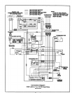
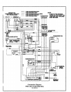
Electrical Connections
All wiring must be done In accordance with the
National Electrical Code (NEC), ANSl/NFPA No. 70
(latest edition); Canadian Electrical Code CSA C22.2
Part I (latest edition); or local codes, where they
prevail. Any alteration of internal wiring will void
certification and warranty.
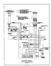
Units are factory wired for a 230 volt power supply. If
power supply is 208 volts, it will be necessary to
change a wire connection on unit transformer from
240 volt terminal to 208 volt terminal as shown on the
wiring diagram.