


PARTNO. ] 41194D094 ] DATE ] 4-15-94 ] SUPERSEDES ] NEW ] PAGE6 OF 10
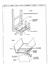
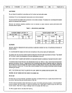
If an installation is madein which it is more desirabletomount thefilter exterior tothe unit, in the return duct work,or
otherwise, eitherthe permanent filter suppliedor a disposable filter may be used. If a disposable filter is used, the
minimum area required is as follows:
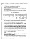
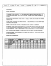
MODELNO, FILTERAREA(MIN.)
PWC182 480 sq. in,
PWC242 480 sq. in.
PWC302 480 sq. in.
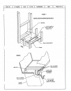
THERMOSTAT
The room thermostatshouldbe locatedonan insidewallwhereit will not be subject todrafts, sun exposureor heat
fromelectrical fixtures or appliances. Followthe manufacturer's instructions enclosedwith thethermostat for general
installationprocedures. Color codedinsulated wires (# !8 AWG)should be usedto connectthe thermostat tothe unit.
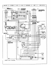
POWERAND CONTROLWIRING
ELECTRICALCONNECTIONS
ALL WIRINGSHOULDBEDONEIN ACCORDANCEWITH NATIONALELECTRICALCODE,ANSI/NFPANo. 70 (LATEST
EDITION).IN CANADACSA C22.2 Part 1 (LATESTEDITION),ORWITH LOCALCODES,WHERETHEY PREVAIL:
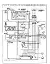
Usewiringwithatemperaturelimitationof 75°C rain. Runthe208or 230 volt,60 hertzelectric powersupplythrough
a fused disconnectswitch to the controlboxof the unit andconnectas showninthe wiringdiagram located on the in-
side ofthe control access panel.
The unit must beelectricallygrounded in accordancewithlocal codesor in the absenceof localcodeswith the Na-
tional Electric CodeANSI/NFPA No. 70 (latest edition)or CSAC22.2 Part 1 (latest edition).
Powersupplyto the unit must be N.E.C. Class1, and must complywith all applicable codes.A fused disconnect
switch should be field providedfor the unit. Theswitchmust be separatefrom all othercircuits.If any of the wire
supplied with the unit must be replaced, replacementwire must be of the type shown onthe wiringdiagram.
Electricalwiring must be sized to minimumcircuitampacitymarked on theunit. USECOPPERCONDUCTORSONLY.
Eachunit must bewired with a separatebranchcircuitand be properlyfused.
SEQUENCEOFUNIT OPERATION
COOLING- Whenthe thermostatisinthecoolingmode,the 0 circuitispoweredwhichenergizesthereversing valve.
Uponcoolingdemand,the thermostat closescircuitRto YandG. ClosingR toY closesthe unit contactor,startingthe
compressorandoutdoorfan. Thethermostatautomatically closesRto Gcircuitwhichalsobrings ontheindoor blower
atthe sametime. Uponsatisfying coolingdemand,the thermostat will openthe abovecircuitsand openthe maincon-
tactor, stoppingthe compressorandoutdoorfan. If the unit is equippedwith a time delay, the blower will coritinueto
operatefor 90 seconds which improvessystemefficiency.
HEATING- Uponheating demand the thermostatclosescircuitR to Y closingthe unitcontactor,starting the com-
pressor andoutdoorfan. Thereversing valveis.no.t-energizedin the heating mode.Thethermostatagainautomatical-
ly brings on the indoorblower at the sametime. Thesecondstage of the thermostatclosescircuftRto W closingthe
unit sequencers, bring theauxiliary electric heaton. Uponsatisfying heating demandthe thermostatopens abovecir-
cuitsand stops unit operation.
i
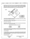
DEFROSTCYCLE- if outdoor ambient conditions are such that frost forms on theoutdoorcoil, the defrost control
monitorsthe need for andinitiatesandterminates defrostcycles as neccessaryto maintain systemperformance. The
defrost controlis time/temperature initiated and temperatureterminatedwith a maximum defrost time (time-out) of
10 minutes. Time betweendefrost cycles is pre-set at 60 minute intervals at the factory, but can be field adjusted to
30, 80, or 90 minutes. Seeillustralion for field adjustment of defrost timing. For best performancein RegionIV, the
PWC242defrost interval should be adjusted to 30 minutes.