


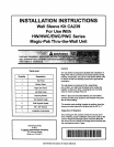

PARTNO. I 41194BOg6I DATE I 2-1-96 I SUPERSEDESI 411940094 I PAGE3OFIO
I
LOCATION
Thedesignis certifiedfor through-the-wallinstallationonly. Theinteriorportionsof theunit may besurroundedbya
closetwith clearancestocombustiblematerial held to 0" at sides,0" top and O" frontof the plenum.
Thegrille sideofthe unitmay beflush with orextendbeyondthe faceof theexteriorwall, butshouldnotberecessed
morethan two(2) inchesfrom theface ofthe buildingand shouldnotbe obstructedwithtrees, landscapematerials,
or buildingstructure.
Thereis nominimumclearancerequiredonlocatinga unittoaninteriorcornerofa building. If theunitis tobeenclos-
ed, provisionsshouldbemadeallowingaccessto theindoorsideof the unitfor changingfilters.and forinspection.At
least33" of unobstructedspaceshouldbe providedin front of the indoorside. whetherenclosedor noL to permit
removalof the coolingchassisshouldrepairsor inspectionbe required.
If this unit is installedin a residentialgarageit must be locatedor protectedtoavoidph_,sicaldamageby vehicles.
Thisunit must be installedso that no electricalcomponentsare exposedto water.
INSTALLATION
CAUTION:THESLEEVEIS NOTINTENDEDAS THESOLESUPPORTFORTHEUNIT. ANADDITIONALSUPPORTMUST
BE PROVIDEDNEARTHE RETURNOPENINGON THE UNIT FOR ADEQUATESUPPORT.THE USE OF VIBRATION
ISOLATIONMATERIALBETWEENTHE UNIT AND THE SUPPORTIS RECOMMENDED,
CAUTION:THIS UNITMUST BEINSTALLEDLEVELFORPROPERDRAINAGEOFTHE CHASSISBASEPANANDUNIT
DRAINPAN.
WITHOUTWALLSLEEVE
Measurethesizeofthe unitandprovideanopeningin anoutsidewall thatwill accepttheunit. Localordinancesmay
require a steel lintel to supportthe wall abovethe opening. Thisopeningmust besquare in all corners.
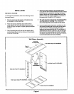
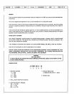
Positionthe unitsothat the grilleson the outsidefaceofthe unit areflush or extendbeyondthe faceofthe exterior
wall,but notrecessedmorethantwo (2) inchesfromthefaceof the building.PROVIOEA SUPPORTUNDERTHE UNIT
INSIDETHE BUILDING.Makesure thatthe insidesupportdoesnot blockthereturnair. The unitshouldbe installed
level.
Sealthe spacebetweentheunit and the buildingopeningusinga non-hardeningcaulkingcompound.Theseal must
beweather-tightto prevententranceof moistureandwater intothe building.Make sure the drainholesin the base
are notpluggedwith caulking.
WITH WALL SLEEVE
Seethe installationinstructionspacked with Ihe wall sleeveto assembleand mountin a wall. Make sure that the
gasketsattachedtothe sleeveare notdamaged.Assurethat the unitis completelyseatedagainstthegasketsonthe
wall sleeve.
Sealspacebetweenwall sleeveand buildingopeningusingnon-hardeningcaulkingcompound.Thisseal must be
watertight.
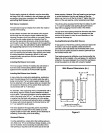
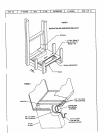
CONDENSATEDRAIN
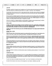
Install the plasticdraintube(furnished)overthe5/8" O.O. fittingwelded tothe condensatepan. Connectotherend
of thedraintubeto trappeddrain line(See Figure2). Theplasticdrain connectionto thechassisbaseis providedso
thatit may bedisconnectedfromthepermanentdrain tubingin the baseof unitin theeventit becomesnecessaryto
removethe chassisassembly.
L
The drain line should pitch gradualtydownwardat least 1" per 10 footof horizontalrun to the opendrain.
Be certainthat the plasticdrain tubing hastree drainageand is notcrimpedor flattenedat anybend.