


Part No. 30790F089 Date 6-1-89
Supersedes 30790G082 Page_of 12
INSTALLATION
Before sliding unit into sleeve, remove 5 screws and washers from top panel. Slide unit into sleeve until the
angle on top of the unit lines up with the top flange of the sleeve, and should almost touch. Fasten unit
to sleeve with the 5 screws and washers above.
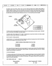
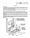
Condensate and Defrost Drain
The condensate drain trap furnished with the unit is a copper tube assembly and is furnished with three
pieces of plastic tubing.
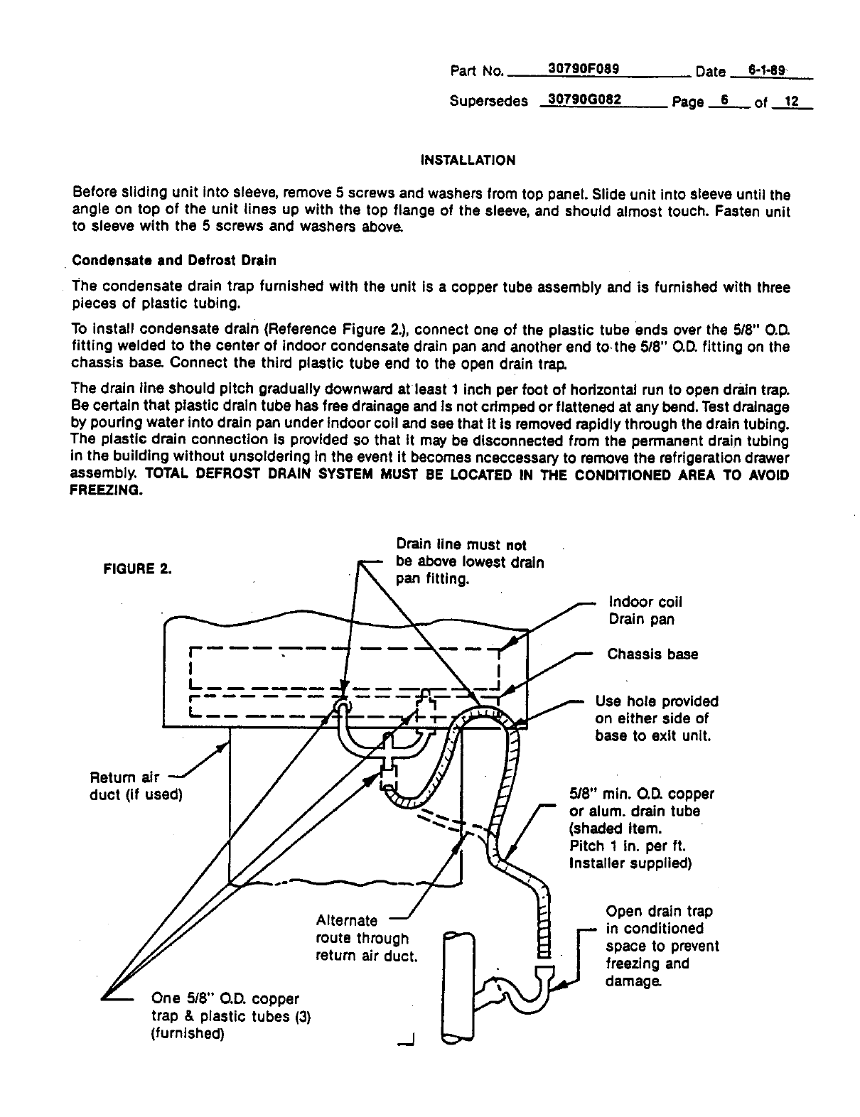
To install condensate drain (Reference Figure 2.), connect one of the plastic tube ends over the 5/8" O.D.
fitting welded to the center of indoor condensate drain pan and another end to.the 5/8" O.D.fitting on the
chassis base. Connect the third plastic tube end to the open drain trap,
The drain line should pitch gradually downward at least 1 inch per foot of horizontal run to open drain trap.
Be certain that plastic drain tube has free drainage and Is not cdmpad or flattened at any bend. Test drainage
by pouring water into drain pan under indoor coil and see that It Is removed rapidly through the drain tubing.
The plastic drain connection Is provided so that tt may be disconnected from the permanent drain tubing
in the building without unsoldering tn the event It becomes nceccesaary to remove the refrigeration drawer
assembly. TOTAL DEFROST DRAIN SYSTEM MUST BE LOCATED IN THE CONDITIONED AREA TO AVOID
FREEZING.
FIGURE 2.
Drain line must not
be above lowest drain
pan fitting.
i,ii_ II •
I
I
r-w
|
Indoor coil
Drain pan
Chassis base
Use hole provided
on either side of
base to exit unit.
Retum air
duct (if used)
5/8" rain. O.D. copper
or alum. drain tube
(shaded Item.
Pitch 1 In. per ft.
Installer supplied)
One 5/8" O.D. copper
trap & plastic tubes (3)
(furnished)
Alternate
route through
return air duct.
/
Open drain trap
in conditioned
space to prevent
freezing and
damage.