


I PA.TNoI .tt9..o96I DATE12196 I SUPERSEDESI ,rig.DO9.I PAGE,O.tO
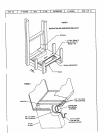
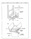
It an installation is made in which it is more desirableto mount the filter exterior tothe unit, in the return duct work, or
olherwise, either the permanent filter supplied or a disposable filter may be used. If a disposable filter is used, the
minimum area required is as follows:
MOOELNO. FILTERAREA(MtN.)
PWC 182 480 sq. in.
PWC242 480 sq. in.
PWC302 480 sq. in.
THERMOSTAT
The room thermostatshouldbe locatedonan insidewall whereit wilt not besubjecttodrafts, sun exposureor heat
from electricalfixturesorappliances.Followthemanufacturer'sinstructionsenclosedwiththethermostatforgeneral
installationprocedures.Colorcodedinsulatedwires(#18 AWG)shouldbeusedtoconnectthethermostattothe unit.
POWERAND CONTROLWIRING
ELECTRICALCONNECTIONS
ALLWIRINGSHOULDBEDONEIN ACCORDANCEWITH NATIONALELECTRICALCODE,ANSI/NFPA NO.70 (LATEST
EDITION).IN CANADA(_SAC22.2 Part 1 (LATESTEDITION),ORWITH LOCAL CODES,WHERETHEY PREVAIL.
NOTE:UNITSAREFACTORYWIREDFORA 230 VOLTPOWERSUPPLY. IF POWERSUPPLYIS 208 VOLTS. IT WILL
BENECESSARYTOCHANGEAWIRE CONNECTIONONUNIT TRANSFORMERFROM240V TERMINALTO20SV TER-
MINAL AS SHOWNON WIRING DIAGRAM.
Usewiringwitha temperaturelimitationof 75°C rain. Runthe 208 or 230 volt,60 hertzelectricpowersupplythrough
a fuseddisconnectswitchto thecontrolboxof theunitandconnectas showninthewiringdiagramlocatedon the in-
sideof the controlaccesspanel.
The unit mustbe electricallygroundedin accordancewith local codesor in the absenceof local codeswith the Na-
tionalElectricCodeANSI/NFPA No. 70 (latestedition)or CSAC22.2 Part 1 (latestedition).
Powersupplyto the unit must be N.E.C. Class 1, and must complywith all applicablecodes.A fused disconnect
switchshouldbe field providedfor the unit. The switchmust be separatefromall othercircuits. If anyof the wire
suppliedwith the unit must be replaced, replacementwire must be of the type shownon the wiring diagram.
Electricalwiringmustbe sized tominimumcircuitampacitymarkedon the unit. USECOPPERCONDUCTORSONLYI
Eachunit must bewired with a separatebranchcircuitand be properlyfused.
SEQUENCEOFUNIT OPERATION
COOLING- WhenthethermostatisIn the coo[ingmode,theOcircuitis poweredwhichenergizesthe reversing valve.
Uponcoolingdemand,the thermostatclosescircuitR toYand G.ClosingRtoY closesthe unitcontactor,startingthe
compressorandoutdoorfan. ThethermostatautomaticallyclosesRto Gcircuitwhichalsobringsontheindoorblower
at thesametime. Uponsatisfyingcoolingdemand,the thermostatwillopentheabovecircuitsandopenthe maincon-
tactor,stoppingthecompressorand outdoorfan. If the unitis equippedwith a time delay,the blowerwillcontinueto
operate.for 90 secondswhich improvessystemefficiency.
HEATING- Uponheatingdemandthe thermostatclosescircuit R to Y closingthe unitcontactor,startingthe com-
pressorand outdoorfan. The reversing valveisnotenergizedin theheating mode.Thethermostatagainautomatical-
ly bringsontheindoorblower at thesametime. Thesecondstageof thethermostatclosescircuit Rto W closingthe
unitsequencers,bringtheauxiliaryelectricheaton. Uponsatisfyingheatingdemandthethermostatopensabovecir-
cuits and stopsunitoperation.
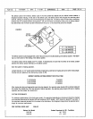
DEFROSTCYCLE- If outdoor ambient conditionsare such that frost formson the outdoorcoil, the defrost control
monitorsthe need for andinitiates and terminatesdefrost cyclesas neccessaryto maintain system performance.The
defrost controlis time/temperatureinitiated and temperature terminated with a maximum defrost time (time-out)of
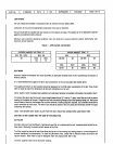
10 minutes. Timebetweendefrost cyclesispre-set at 60 minuteintervalsat thefactory, but canbe field adjustedto
30, 60, or 90 minutes.See illustrationfor field adjustmentof defrosttiming.For best performancein RegionIV, the
PWC242defrostinterval shouldbeadjustedto30 minutes.