


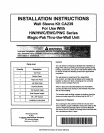
INSTALLATION
Wall Sleeve Assembly
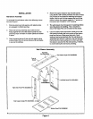
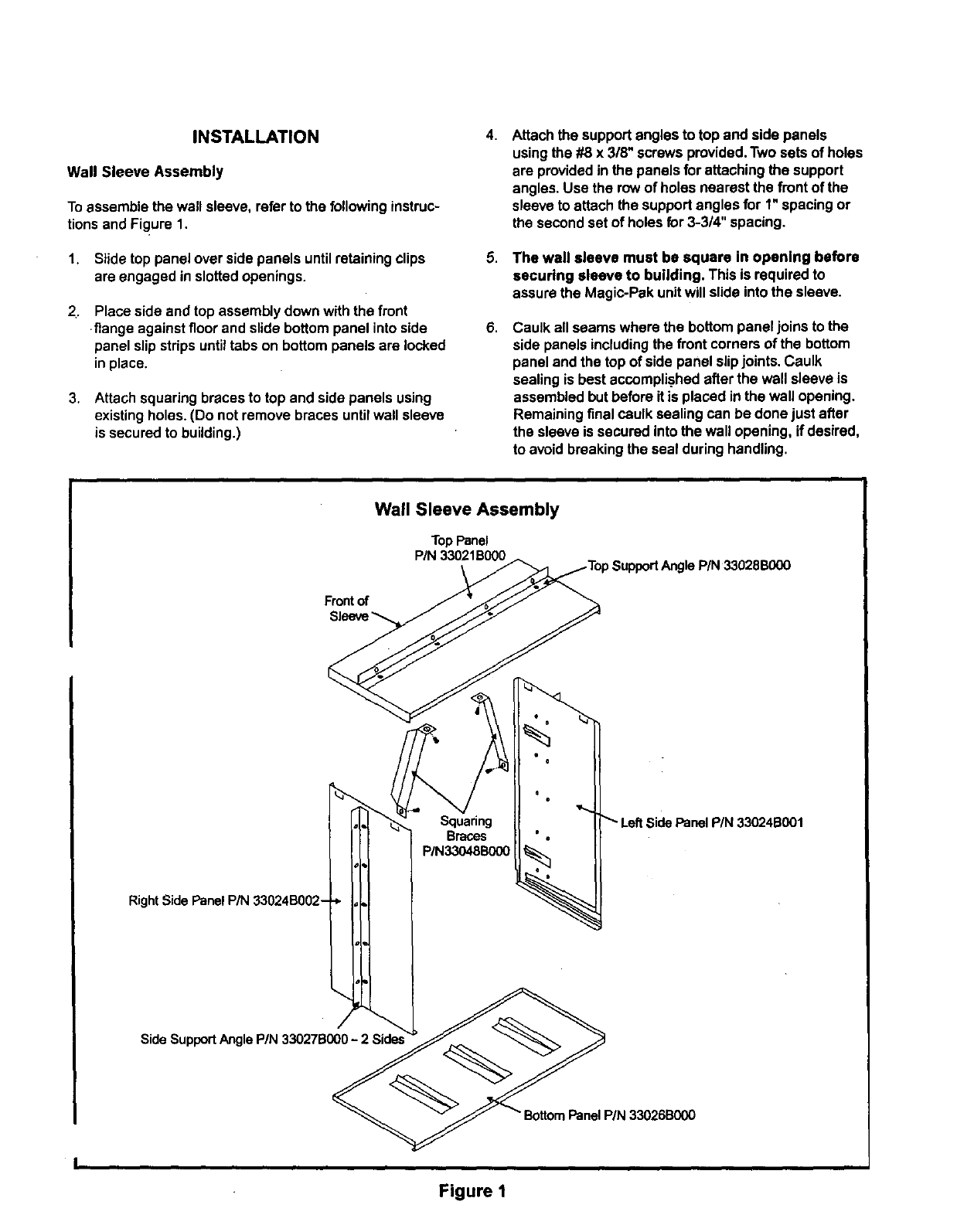
Toassemble the wall sleeve, refer tothe followinginstruc-
tionsand Figure 1.
1. Slide top panel over side panels untilretaining clips
are engaged in slottedopenings.
2_
Place side and top assemblydown withthe front
flange against floorand slide bottom panel intoside
panelslip stripsuntiltabs on bottompanels are locked
inplace.
3. Attach squaring bracesto top and side panels using
existingholes. (Do not remove braces untilwall sleeve
issecured to building.)
4.
8.
Attachthe support anglesto top and side panels
usingthe #8 x 318"screwsprovided.Two sets of holes
are providedin thepanels for attaching the support
angles. Use the rowof holesnearest the frontof the
sleeveto attach the supportangles for 1"spacing or
the secondset of holesfor 3-3/4" spacing.
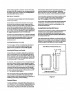
The wall sleeve must be square in opening before
securing sleeve to building. This is requiredto
assure the Magic-Pak unitwill slideintothe sleeve.
Caulk all seams where the bottompanel joins tothe
side panelsincludingthe front corners ofthe bottom
panel and the top ofside panel slipjoints. Caulk
sealing is best accomplishedafterthe wall sleeve is
assembledbutbefore Ris placed inthe wall opening.
Remainingfinal caulk sealing can be done just after
the sleeve issecured intothe wall opening, ifdesired,
to avoidbreakingthe seal duringhandling.
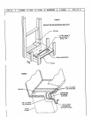
Wall Sleeve Assembly
TopPanel
P/N33021B000
Frontof
RightSide PanelP/N 33024B002-
Squaring
Braces
P/N33048B000
LeftSide Panel P/N 33024B001
Side SupportAngle PIN 33027BG00- 2 Side=
Figure I