


Part No. 30790F089 Date 6-1-89
Supersedes 30790G082 Page_of 12
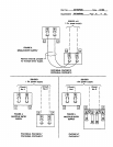
Thermostat
This unit requires special thermostat for operation. See product specification sheets or label on unit for
manufacture's part number. Install the thermostat according to directions furnished with It. Select a loca-
tion in a room having the most wall or window area exposed to the outsid_ Locate on an inside wall, away
from drafts, sunlight or any heat producing appliances. Connect thermostat wires to pigtail leads on unit
with wire nuts following wire diagrams attached to unit.
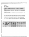
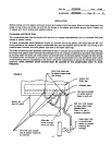
Air Filter
This unit is supplied with a permanent type high filtration filter, located in front of the indoor coil. If an In-
tallation is made in which it Is more desirable to mount the filter extedor to the unit In the return duct, the
permanent filter supplied can be used or a disposable filter may be used. If a different filter or filters are
used the minimum total filter area required is 375 eq. in. of nominal 112inch thick media, if a remote filter
is Installed, the permanent filter supplied with this unit must be removed.
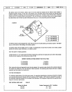
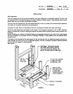
Duct Work
Provide duct work sufficiently large enough to handle the air volume at the total external static pressure
not exceeding the rating of the unit published in the Product Specification sheet for the rated cooling air
volume.
Connect supply duct to top of unit using canvas connections or other flexible connection to prevent sound
transmission Into the duct system.
To connect the return duct to the unit, use e straight piece of duct 21 _" by 9".
Insert duct into return opening in bottom of unit and flange duct over existing flanges around opening In-
side unit. Make sure that all sides of the duct are flanged over to permit removal of cooling chassis If re-
quired. Use a flexible connection to attach remainder of return air duct.
Adjustments
No adjustments are required or should be attempted regarding any of the components of the heat pump
chassis and supplementary electdc heaters.
The unit should be checked to see that none of the wiring is loose or missing. The plug-in electrical connec.
tors between the cooling chassis and the main control compartment should be checked to make sure the
plugs are firmly seated and none of the wires are loose.