


Page 8
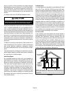
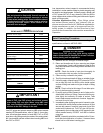
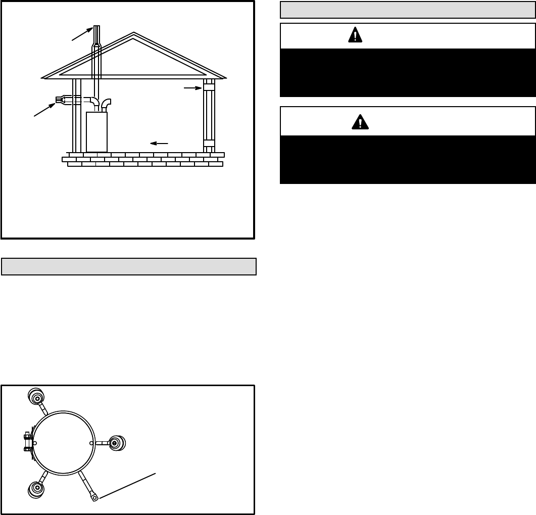
FIGURE 9
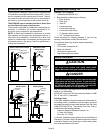
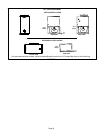
EQUIPMENT IN CONFINED SPACE -
ALL AIR FROM OUTSIDE
OUTLET AIR
INLET AIR
NOTE-Each air duct opening shall have a free area of at least one
square inch per 2,000 Btu (645mm
2
per .59kW) per hour of the total
input rating of all equipment in the enclosure. If the equipment room
is located against an outside wall and the air openings communi
cate directly with the outdoors, each opening shall have a free area
of at least 1 square inch per 4,000 Btu (645mm
2
per 1.17kW) per
hour of the total input rating of all other equipment in the enclosure.
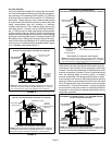
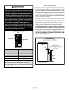
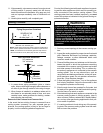
ROOF TERMINATED
EXHAUST PIPE
SIDE WALL
TERMINATED
EXHAUST PIPE
(ALTERNATE
LOCATION)
FURNACE
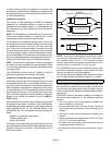
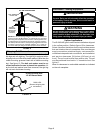
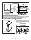
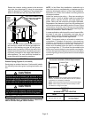
Shipping Bolt Removal
Units with 1/2 hp blower motor are equipped with three flex
ible legs and one rigid leg. The rigid leg is equipped with a
shipping bolt and a flat white plastic washer (rather than the
rubber mounting grommet used with a flexible mounting
leg). See figure 10. The bolt and washer must be re
moved before the furnace is placed into operation. Af
ter the bolt and washer have been removed, the rigid leg
will not touch the blower housing.
FIGURE 10
RIGID LEG
(Remove shipping bolt
and washer)
EL296 Furnaces with
1/2 HP Blower Motor
Installation - Setting Equipment
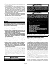
WARNING
Do not connect the return air duct to the back of the
furnace. Doing so will adversely affect the operation
of the safety control devices, which could result in
personal injury or death.
WARNING
Blower access panel must be securely in place when
blower and burners are operating. Gas fumes, which
could contain carbon monoxide, can be drawn into
living space resulting in personal injury or death.
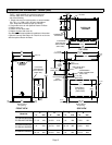
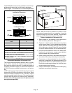
Upflow Applications
The EL296UHE gas furnace can be installed as shipped
in the upflow position. Refer to figure 12 for clearances.
Select a location that allows for the required clearances
that are listed on the unit nameplate. Also consider gas
supply connections, electrical supply, vent connection,
condensate trap and drain connections, and installation
and service clearances [24 inches (610 mm) at unit
front]. The unit must be level from side to side. The unit
may be positioned from level to ½” toward the front. See
figure 11.
Allow for clearances to combustible materials as indicated
on the unit nameplate.