


Page 29
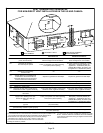
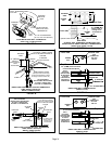
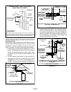
7 - If intake and exhaust piping must be run up a side wall
to position above snow accumulation or other ob
structions, piping must be supported every 24”
(610MM) as shown in figures 36 and 37. In addition,
close coupled wall termination kits must be extended
for use in this application. See figures 44 and 45.
When exhaust and intake piping must be run up an
outside wall, the exhaust piping must be terminated
with pipe sized per table 8.The intake piping may be
equipped with a 90° elbow turndown. Using turndown
will add 5 feet (1.5m) to the equivalent length of the
pipe.
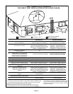
8 - A multiple furnace installation may use a group of up to
four terminations assembled together horizontally, as
shown in figure 41.
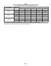
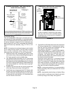
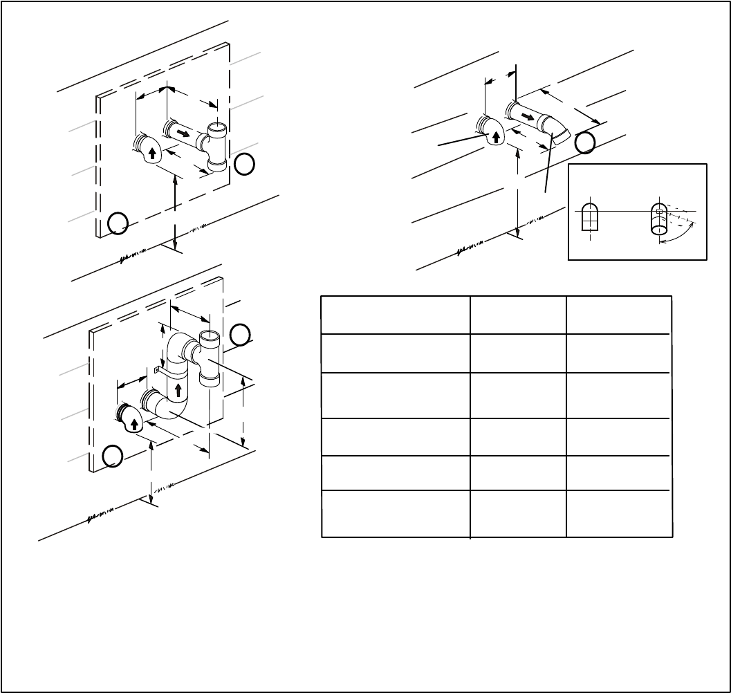
C
A
E
D
B
A
B
D
D
B
C
A
C
12”
1
1
2
2
2” (51MM)
Vent Pipe
3” (76MM)
Vent Pipe
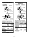
A- Clearance above
grade or average snow
accumulation
B-Horizontal
separation between
intake and exhaust
C-Minimum from
end of exhaust to
inlet of intake
D-Exhaust pipe length
E-Wall support distance
from top of each pipe
(intake/exhaust)
12” (305MM) Min.
12” (305MM) Min.
6” (152MM) Min.
24” (610MM) Max
9” (227MM) Min.
12” (305MM) Min.
16” (405MM) Max.
6” (152MM) Max.
6” (152MM) Min.
24” (610MM) Max
9” (227MM) Min.
12” (305MM) Min.
20” (508MM) Max.
6” (152MM) Max.
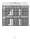
TABLE 9
FIGURE 35
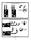
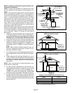
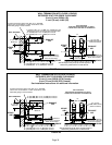
1
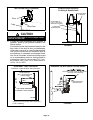
The exhaust termination tee should be connected to the 2” or 3” PVC flue pipe as shown in the illustration. Do
not use an accelerator in applications that include an exhaust termination tee. The accelerator is not required.
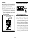
2
As required. Flue gas may be acidic and may adversely affect some building materials. If a side wall vent
termination is used and flue gases will impinge on the building materials, a corrosion-resistant shield (24 inches
square) should be used to protect the wall surface. If optional tee is used, the protective shield is recommende
d. The shield should be constructed using wood, sheet metal or other suitable material. All seams, joints,
cracks, etc. in affected area, should be sealed using an appropriate sealant.
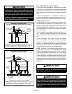
3
Exhaust pipe 45° elbow can be rotated to the side away from the combustion air inlet to direct exhaust away
from adjacent property. The exhaust must never be directed toward the combustion air inlet.
Front View of
Intake and Exhaust
Intake
Exhaust
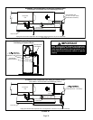
3
Intake
Exhaust
Alternate Terminations
(Tee & Forty-Five Degree Elbows Only)