


Page 16
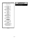
Resize the common venting system to the minimum
vent pipe size determined by using the appropriate
tables in Appendix G. (These are in the current stan
dards of the National Fuel Gas Code ANSI Z223.1.
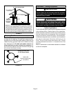
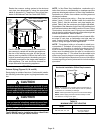
CHIMNEY
OR GAS
VENT
(Check sizing
for water
heater only)
FURNACE
(Replaced
by EL296)
WATER
HEATER
OPENINGS
(To Adjacent
Room)
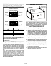
If an EL296UHE furnace replaces a furnace which
was commonly vented with another gas appliance,
the size of the existing vent pipe for that gas ap
pliance must be checked. Without the heat of the
original furnace flue products, the existing vent pipe
is probably oversized for the single water heater or
other appliance. The vent should be checked for
proper draw with the remaining appliance.
FIGURE 21
REPLACING FURNACE THAT
WAS PART OF A COMMON
VENT SYSTEM
Exhaust Piping (Figures 22, 24 and 25)
Route piping to outside of structure. Continue with installa
tion following instructions given in piping termination sec
tion.
CAUTION
Do not discharge exhaust into an existing stack or
stack that also serves another gas appliance. If verti
cal discharge through an existing unused stack is re
quired, insert PVC pipe inside the stack until the end
is even with the top or outlet end of the metal stack.
CAUTION
The exhaust vent pipe operates under positive pres
sure and must be completely sealed to prevent leak
age of combustion products into the living space.
Vent Piping Guidelines
The EL296UHE can be installed as either a Non-Direct
Vent or a Direct Vent gas central furnace.
NOTE - In Non‐Direct Vent installations, combustion air is
taken from indoors or ventilated attic or crawlspace and flue
gases are discharged outdoors. In Direct Vent installations,
combustion air is taken from outdoors and flue gases are
discharged outdoors.
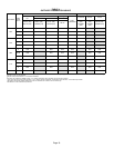
Intake and exhaust pipe sizing -- Size pipe according to
tables 3 and
5. Count all elbows inside and outside the
home. Table 3 lists the minimum vent pipe lengths per
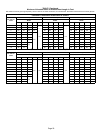
mitted. Table 5 lists the maximum pipe lengths permitted.
Regardless of the diameter of pipe used, the standard roof
and wall terminations described in section Exhaust Piping
Terminations should be used. Exhaust vent termination
pipe is sized to optimize the velocity of the exhaust gas as
it exits the termination. Refer to table 8.
In some applications which permit the use of several differ
ent sizes of vent pipe, a combination vent pipe may be
used. Contact Lennox' Application Department for assis
tance in sizing vent pipe in these applications.
NOTE - The exhaust collar on all models is sized to ac
commodate 2” Schedule 40 vent pipe. In horizontal ap
plications, any transition to exhaust pipe larger than 2”
must be made in vertical runs of the pipe. Therefore a 2”
elbow must be added before the pipe is transitioned to
any size larger than 2”. This elbow must be added to the
elbow count used to determine acceptable vent lengths.
Contact the Application Department for more information
concerning sizing of vent systems which include multiple
pipe sizes.
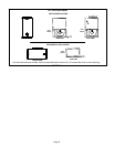
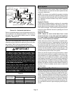
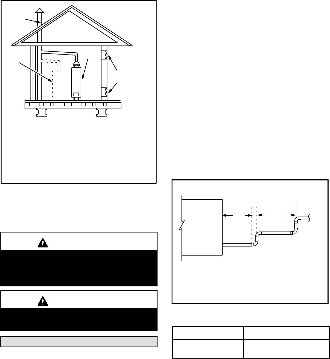
FIGURE 22
Horizontal Installation Offset Requirements
NOTE - Exhaust pipe MUST be glued to furnace exhaust fittings.
NOTE - All horizontal runs of exhaust pipe must slope back to
ward unit. A minimum of 1/4” (6mm) drop for each 12” (305mm)
of horizontal run is mandatory for drainage.
NOTE - Exhaust piping should be checked carefully to make
sure there are no sags or low spots.
Exhaust Pipe
Horizontal
Gas Furnace
12” Min.
12” Max.
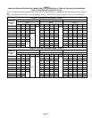
TABLE 3
MINIMUM VENT PIPE LENGTHS
EL296UHE
MODEL
MIN. VENT LENGTH*
045, 070, 090, 110, 135
15 ft. or
5 ft. plus 2 elbows or
10 ft. plus 1 elbow
*Any approved termination may be added to the minimum length listed.