


Page 34
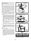
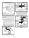
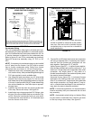
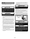
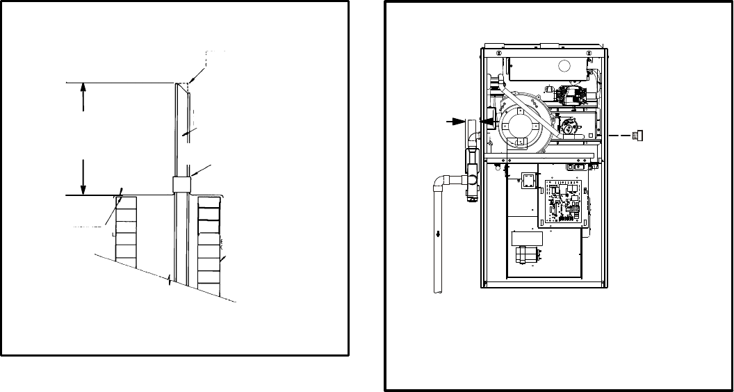
NOTE - Do not discharge exhaust gases directly into any chimney or vent stack. If ver
tical discharge through an existing unused chimney or stack is required, insert piping
inside chimney until the pipe open end is above top of chimney and terminate as illus
trated. In any exterior portion of chimney, the exhaust vent must be insulated.
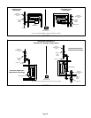
FIGURE 50
STRAIGHT-CUT OR
ANGLE-CUT IN DIRECTION
OF ROOF SLOPE
EXHAUST VENT
1/2” (13MM)
WEATHERPROOF
INSULATION
SHOULDER OF FITTINGS
PROVIDE SUPPORT
OF PIPE ON TOP PLATE
EXTERIOR
PORTION OF
CHIMNEY
INSULATE
TO FORM
SEAL
SHEET
METAL TOP
PLATE
SIZE TERMINATION
PIPE PER TABLE 8.
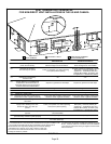
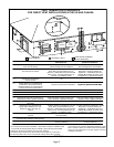
EL296UHE NON-DIRECT VENT APPLICATION
USING EXISTING CHIMNEY
Minimum 12” (305MM)
above chimney top
plate or average snow
accumulation
Condensate Piping
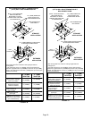
This unit is designed for either right‐ or left‐side exit of con
densate piping in upflow applications. In horizontal applica
tions, the condensate trap must extend below the unit. An
8” service clearance is required for the condensate trap.
Refer to figures 51 and 53 for condensate trap locations.
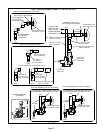
Figure 59 shows trap assembly using 1/2” PVC or 3/4”
PVC.
NOTE - If necessary the condensate trap may be installed
up to 5’ away from the furnace. Use PVC pipe to connect
trap to furnace condensate outlet. Piping from furnace
must slope down a minimum of 1/4” per ft. toward trap.
1 - Determine which side condensate piping will exit the
unit, location of trap, field-provided fittings and length of
PVC pipe required to reach available drain.
2 - Use a large flat head screw driver or a 1/2” drive socket
extension and remove plug (figure 51) from the cold
end header box at the appropriate location on the side
of the unit. Install provided 3/4 NPT street elbow fitting
into cold end header box. Use Teflon tape or appropri
ate pipe dope.
3 - Install the cap over the clean out opening at the base
of the trap. Secure with clamp. See figure 59.
4 - Install drain trap using appropriate PVC fittings, glue
all joints. Glue the provided drain trap as shown in fig
ure 59. Route the condensate line to an open drain.
Condensate line must maintain a 1/4” downward slope
from the furnace to the drain.
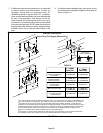
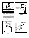
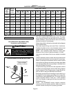
FIGURE 51
CONDENSATE TRAP AND PLUG LOCATIONS
(Unit shown in upflow position)
NOTE - In upflow applications where side return
air filter is installed on same side as the conden
sate trap, filter rack must be installed beyond
condensate trap or trap must be re-located to
avoid interference.
Trap
(same on
right side)
Plug
(same on left side)
1-1/2 in.
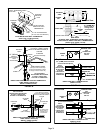
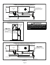
5 - Figures 54 and 56 show the furnace and evaporator
coil using a separate drain. If necessary the conden
sate line from the furnace and evaporator coil can
drain together. See figures 55, 57 and 58.
Upflow furnace (figure 57) - In upflow furnace applica
tions the field provided vent must be a minimum 1” to a
maximum 2” length above the condensate drain outlet
connection. Any length above 2” may result in a
flooded heat exchanger if the combined primary drain
line were to become restricted.
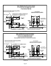
Horizontal furnace (figure 58) - In horizontal furnace
applications the field provided vent must be a mini
mum 4” to a maximum 5” length above the condensate
drain outlet connection. Any length above 5” may re
sult in a flooded heat exchanger if the combined pri
mary drain line were to become restricted.
NOTE - In horizontal applications it is recommended to
install a secondary drain pan underneath the unit and
trap assembly.
NOTE - Appropriately sized tubing and barbed fitting
may be used for condensate drain. Attach to the drain
on the trap using a hose clamp. See figure 52.