


Page 28
Details of Intake and Exhaust Piping Terminations for
Direct Vent Installations
NOTE - In Direct Vent installations, combustion air is tak
en from outdoors and flue gases are discharged to out
doors.
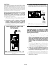
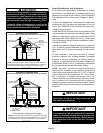
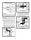
NOTE - Flue gas may be slightly acidic and may adversely
affect some building materials. If any vent termination is
used and the flue gasses may impinge on the building ma
terial, a corrosion-resistant shield (minimum 24 inches
square) should be used to protect the wall surface. If the
optional tee is used, the protective shield is recommended.
The shield should be constructed using wood, plastic,
sheet metal or other suitable material. All seams, joints,
cracks, etc. in the affected area should be sealed using an
appropriate sealant. See figure 35.
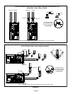
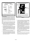
Intake and exhaust pipes may be routed either horizontally
through an outside wall or vertically through the roof. In at
tic or closet installations, vertical termination through the
roof is preferred. Figures 32 through 46 show typical
terminations.
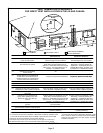
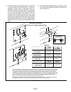
1 - Intake and exhaust terminations are not required to be
in the same pressure zone. You may exit the intake on
one side of the structure and the exhaust on another
side (figure 33). You may exit the exhaust out the roof
and the intake out the side of the structure (figure 34).
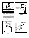
2 - Intake and exhaust pipes should be placed as close
together as possible at termination end (refer to il
lustrations). Maximum separation is 3” (76MM) on roof
terminations and 6” (152MM) on side wall termina
tions.
NOTE - When venting in different pressure zones, the
maximum separation requirement of intake and ex
haust pipe DOES NOT apply.
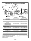
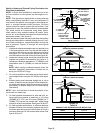
3 - On roof terminations, the intake piping should termi
nate straight down using two 90° elbows (See figure
32).
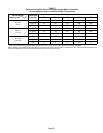
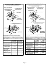
4 - Exhaust piping must terminate straight out or up as
shown. A reducer may be required on the exhaust pip
ing at the point where it exits the structure to improve
the velocity of exhaust away from the intake piping.
See table 8.
NOTE - Care must be taken to avoid recirculation of ex
haust back into intake pipe.
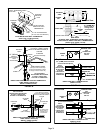
5 - On field-supplied terminations for side wall exit, ex
haust piping may extend a maximum of 12 inches
(305MM) for 2” PVC and 20 inches (508MM) for 3”
(76MM) PVC beyond the outside wall. Intake piping
should be as short as possible. See figures 36 and 37.
6 - On field-supplied terminations, a minimum distance
between the end of the exhaust pipe and the end of
the intake pipe without a termination elbow is 8” and a
minimum distance of 6” with a termination elbow. See
figures 36 and 37.
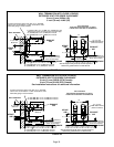
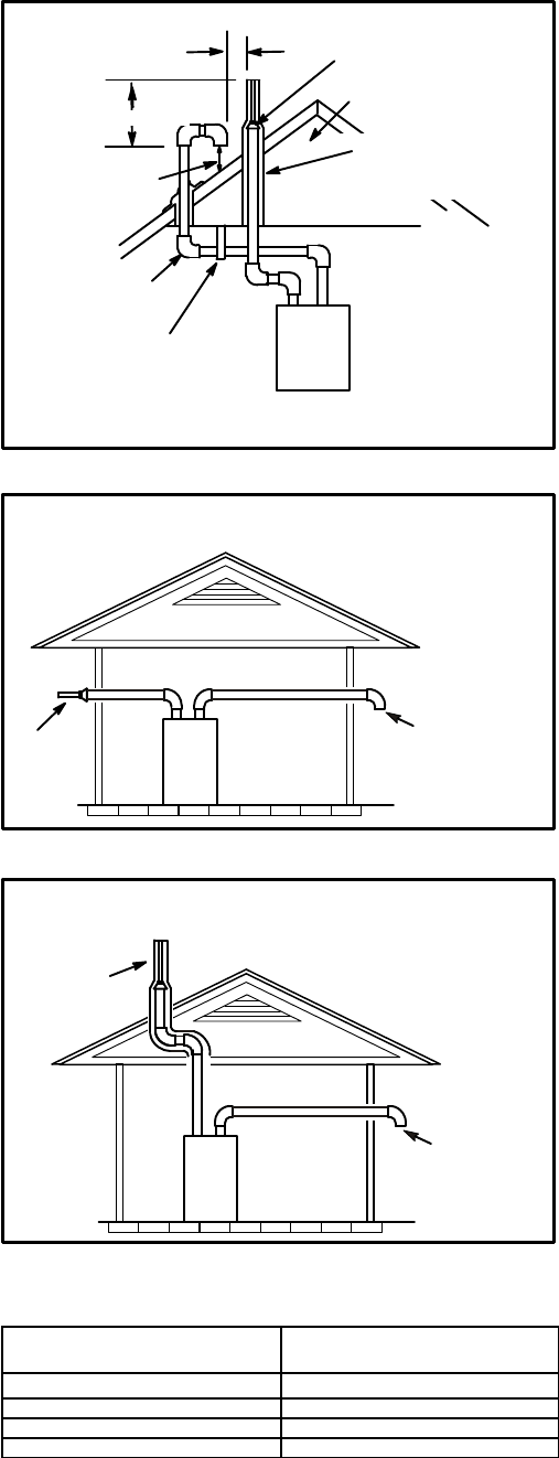
FIGURE 32
UNCONDITIONED
ATTIC SPACE
1/2” (13MM) FOAM
INSULATION IN
UNCONDITIONED
SPACE
SIZE TERMINATION
PIPE PER TABLE 8.
3”(76MM) MAX.
12” (305MM) ABOVE
AVERAGE SNOW
ACCUMULATION
3” (76MM) OR
2” (51MM) PVC
PROVIDE SUPPORT
FOR INTAKE AND
EXHAUST LINES
8” (203MM) MIN
Inches(MM)
DIRECT VENT ROOF TERMINATION KIT
(15F75 or 44J41)
FIGURE 33
Exhaust
Pipe
Furnace
Exiting Exhaust and Intake Vent
(different pressure zones)
Inlet Air
(Minimum 12 in.
305 MM) above
grade or snow
accumulation
FIGURE 34
Roof T
erminated
Exhaust Pipe
Furnace
Exiting Exhaust and Intake Vent
(different pressure zones)
Inlet Air
(Minimum 12 in.
305 MM) above
grade or snow
accumulation
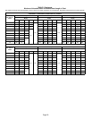
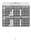
TABLE 8
EXHAUST PIPE TERMINATION SIZE REDUCTION
EL296UHE
MODEL
Termination
Pipe Size
*045 and 070
1-1/2” (38MM)
*090 2” (51MM)
110 2” (51MM)
135 2” (51MM)
*EL296UHE-045, -070 and -090 units with the flush mount termination must
use the 1-1/2”accelerator supplied with the kit.