


Page 50
4 - Move gas valve switch to OFF.
5 - Replace the access panel.
Failure To Operate
If the unit fails to operate, check the following:
1 - Is the thermostat calling for heat?
2 - Are access panels securely in place?
3 - Is the main disconnect switch closed?
4 - Is there a blown fuse or tripped breaker?
5 - Is the filter dirty or plugged? Dirty or plugged filters will
cause the limit control to shut the unit off.
6 - Is gas turned on at the meter?
7 - Is the manual main shut‐off valve open?
8 - Is the internal manual shut‐off valve open?
9 - Is the unit ignition system in lockout? If the unit locks out
again, inspect the unit for blockages.
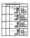
Heating Sequence Of Operation
1 - When thermostat calls for heat, combustion air inducer
starts.
2 - Combustion air pressure switch proves blower opera
tion. Switch is factory set and requires no adjustment.
3 - After a 15-second prepurge, the hot surface ignitor en
ergizes.
4 - After a 20-second ignitor warm-up period, the gas
valve solenoid opens. A 4-second trial for ignition peri
od begins.”
5 - Gas is ignited, flame sensor proves the flame, and the
combustion process continues.
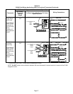
6 - If flame is not detected after first ignition trial, the igni
tion control will repeat steps 3 and 4 four more times
before locking out the gas valve (“WATCHGUARD”
flame failure mode). The ignition control will then auto
matically repeat steps 1 through 6 after 60 minutes.
To interrupt the 60-minute “WATCHGUARD” period,
move thermostat from “Heat” to “OFF” then back to
“Heat”. Heating sequence then restarts at step 1.
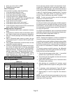
Gas Pressure Adjustment
Gas Flow (Approximate)
TABLE 15
GAS METER CLOCKING CHART
EL296
Unit
Seconds for One Revolution
Natural LP
1 cu ft
Dial
2 cu ft
Dial
1 cu ft
Dial
2 cu ft
DIAL
-045 80 160 200 400
-070 55 110 136 272
-090 41 82 102 204
-110 33 66 82 164
-135 27 54 68 136
Natural-1000 btu/cu ft LP-2500 btu/cu ft
Furnace should operate at least 5 minutes before check
ing gas flow. Determine time in seconds for two revolu
tions of gas through the meter. (Two revolutions assures a
more accurate time.) Divide by two and compare to time
in table 15. If manifold pressure matches table 17 and rate
is incorrect, check gas orifices for proper size and re
striction. Remove temporary gas meter if installed.
NOTE - To obtain accurate reading, shut off all other gas
appliances connected to meter.
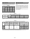
Supply Pressure Measurement
An inlet post located on the gas valve provides access to
the supply pressure. See figure 66. Back out the 3/32 hex
screw one turn, connect a piece of 5/16 tubing and connect
to a manometer to measure supply pressure. See table 17
for supply line pressure.
On multiple unit installations, each unit should be checked
separately, with and without units operating. Supply pres
sure must fall within range listed in table 17.
Manifold Pressure Measurement
NOTE - Pressure test adapter kit (10L34) is available from
Lennox to facilitate manifold pressure measurement.
A manifold pressure post located on the gas valve provides
access to the manifold pressure. See figure 66. Back out
the 3/32 hex screw one turn, connect a piece of 5/16 tubing
and connect to a manometer to measure manifold pres
sure.
To correctly measure manifold pressure, the differential
pressure between the positive gas manifold and the nega
tive burner box must be considered.
1 - Connect the test gauge positive side “+“ to manifold
pressure tap on gas valve as noted above.
2 - Tee into the gas valve regulator vent hose and connect
to test gauge negative “-”.
3 - Ignite unit on low fire and let run for 5 minutes to allow
for steady state conditions.
4 - After allowing unit to stabilize for 5 minutes, record
manifold pressure and compare to value given in table
17.
5 - If necessary, make adjustments. Figure 66 shows
location of high fire and low fire adjustment screws.
6 - Repeat steps 3, 4 and 5 on high fire. See values in
table 17.
NOTE - Shut unit off and remove manometer as soon as an
accurate reading has been obtained. Re-start unit and
check gas valve for gas leaks.