


Page 53
Other Unit Adjustments
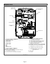
Primary Limit.
The primary limit is located on the heating compartment
vestibule panel. This limit is factory set and requires no ad
justment.
Flame Rollout Switches (Two)
These manually reset switches are located on the front of
the burner box.
Pressure Switch
The pressure switch is located in the heating compartment
on the cold end header box. This switch checks for proper
combustion air inducer operation before allowing ignition
trial. The switch is factory-set and must not be adjusted.
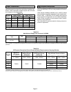
Temperature Rise
Place the unit into operation with a second-stage heating
demand. After supply and return air temperatures have
stabilized, check the temperature rise. If necessary, adjust
the heating blower speed to maintain the temperature rise
within the range shown on the unit nameplate. Increase the
blower speed to decrease the temperature rise. Decrease
the blower speed to increase the temperature rise. Failure
to properly adjust the temperature rise may cause erratic
limit operation.
Electrical
1 - Check all wiring for loose connections.
2 - Check for the correct voltage at the furnace (furnace
operating). Correct voltage is 120VAC +
10%
3 - Check amp-draw on the blower motor with blower ac
cess panel in place.
Unit Nameplate__________Actual__________
Exhaust and Air Intake Pipe
1 - Check exhaust and air intake connections for tightness
and to make sure there is no blockage.
2 - Is pressure switch closed? Obstructed exhaust pipe
will cause unit to shut off at pressure switch. Check ter
mination for blockages.
3 - Obstructed pipe or termination may cause rollout
switches to open. Reset manual flame rollout switches
on burner box assembly if necessary.
Heating Sequence of Operation
Electronic Ignition
The two-stage, variable speed integrated control used in
EL296UHE units has an added feature of an internal Watch
guard control. The feature serves as an automatic reset de
vice for ignition control lockout caused by ignition failure. Af
ter one hour of continuous thermostat demand for heat, the
Watchguard will break and remake thermostat demand to
the furnace and automatically reset the control to begin the
ignition sequence.
NOTE - The ignition control thermostat selection DIP switch is
factory-set in the “TWO-STAGE” position.
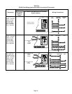
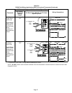
Applications Using a Two-Stage Thermostat
A - Heating Sequence -- Integrated Control Thermostat
Selection DIP Switch 1 OFF in “Two-Stage” Position
(Factory Setting)
1 - On a call for heat, thermostat first-stage contacts close
sending a signal to the integrated control. The inte
grated control runs a self‐diagnostic program and
checks high temperature limit switches for normally
closed contacts and pressure switches for normally
open contacts. The combustion air inducer is ener
gized at low speed.
2 - Once the control receives a signal that the low pres
sure switch has closed, the combustion air inducer be
gins a 15-second pre-purge in low speed.
NOTE - If the low fire pressure switch does not close
the combustion air inducer will switch to high fire. After
a 15 second pre-purge the high fire pressure switch
will close and the unit will begin operation on high fire.
After 10 to 20 seconds of high fire operation the unit
will switch to low fire..
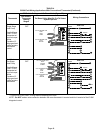
3 - After the pre-purge is complete, a 20-second initial ig
nitor warm-up period begins. The combustion air in
ducer continues to operate at low speed.
4 - After the 20-second warm-up period has ended, the gas
valve is energized on low fire (first stage) and ignition oc
curs. At the same time, the control module sends a sig
nal to begin an indoor blower 30-second ON-delay.
When the delay ends, the indoor blower motor is ener
gized on the low fire heating speed, the HUM contacts
close energizing the humidifier and 120V ACC termi
nal is energized. The furnace will continue this opera
tion as long as the thermostat has a first-stage heating
demand.
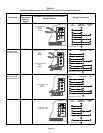
5 - If second-stage heat is required, the thermostat sec
ond-stage heat contacts close and send a signal to the
integrated control. The integrated control initiates a
30-second second-stage recognition delay.
6 - At the end of the recognition delay, the integrated con
trol energizes the combustion air inducer at high
speed. The control also checks the high fire (second
stage) pressure switch to make sure it is closed. The
high fire (second stage) gas valve is energized and the
indoor blower motor is energized for operation at the
high fire heating speed.
7 - When the demand for high fire (second stage) heat is
satisfied, the combustion air inducer is switched to the
low-fire heating speed and the high-fire (second
stage) gas valve is de-energized. The low-fire (first
stage) gas valve continues operation. The indoor
blower motor is switched to the low-fire heating speed.
8 - When the thermostat demand for low-fire (first stage)
heat is satisfied, the gas valve is de-energized and the
field-selected indoor blower off delay begins. The
combustion air inducer begins a 5-second post-purge
period.
9 - When the combustion air post-purge period is com
plete, the inducer, the HUM contacts as well as the
120V ACC terminals are de-energized. The indoor
blower is de-energized at the end of the off delay.