


Page 13
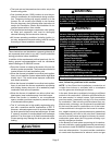
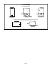
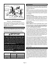
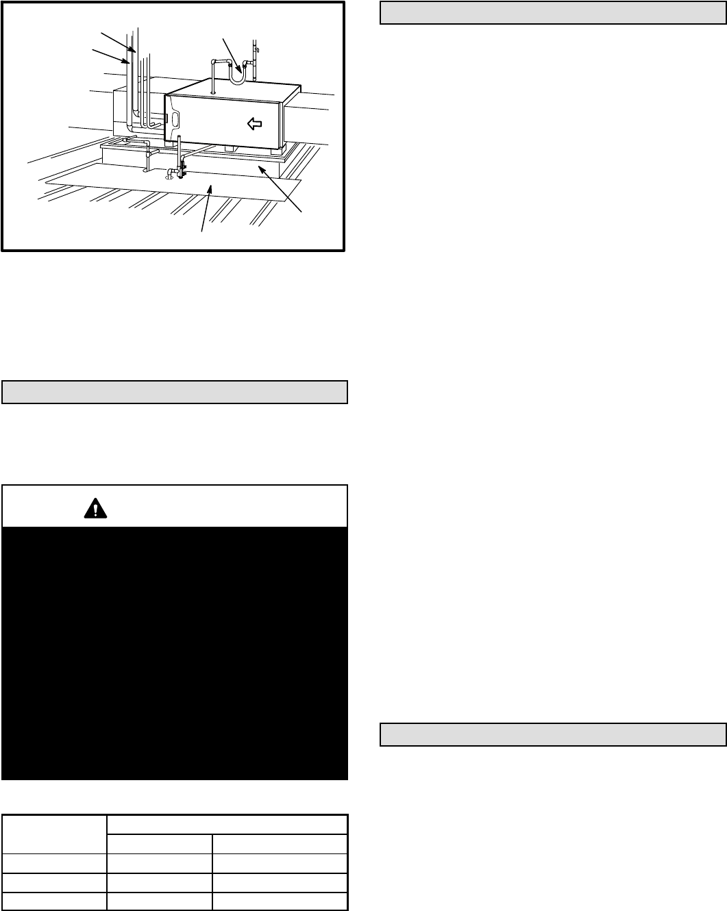
*Gas connector may be
used for Canadian
installation if accept
able by local authority
having jurisdiction.
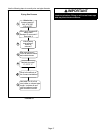
FIGURE 19
*GAS CONNECTION
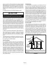
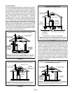
RAISED
PLATFORM
SERVICE PLATFORM
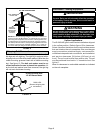
INTAKE PIPE
EXHAUST PIPE
Return Air -- Horizontal Applications
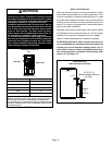
Return air may be brought in only through the end of a fur
nace installed in the horizontal position. The furnace is
equipped with a removable bottom panel to facilitate
installation. See figure 15.
Filters
This unit is not equipped with a filter or rack. A field-pro
vided high velocity rated filter is required for the unit to oper
ate properly. Table 1 lists recommended filter sizes.
A filter must be in place whenever the unit is operating.
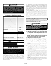
IMPORTANT
If a highefficiency filter is being installed as part of
this system to ensure better indoor air quality, the fil
ter must be properly sized. Highefficiency filters
have a higher static pressure drop than standardef
ficiency glass/foam filters. If the pressure drop is too
great, system capacity and performance may be re
duced. The pressure drop may also cause the limit to
trip more frequently during the winter and the indoor
coil to freeze in the summer, resulting in an increase
in the number of service calls.
Before using any filter with this system, check the
specifications provided by the filter manufacturer
against the data given in the appropriate Lennox
Product Specifications bulletin. Additional informa
tion is provided in Service and Application Note
ACC002 (August 2000).
TABLE 1
Furnace
Cabinet Width
Filter Size
Side Return Bottom Return
17-1/2” 16 X 25 X 1 (1) 16 X 25 X 1 (1)
21” 16 X 25 X 1 (1) 20 X 25 X 1 (1)
24-1/2” 16 X 25 X 1 (2) 24 X 25 X 1 (1)
Duct System
Use industry‐approved standards to size and install the
supply and return air duct system. Refer to ACCA Manual
D. This will result in a quiet and low‐static system that has
uniform air distribution.
NOTE - This furnace is not certified for operation in heating
mode (indoor blower operating at selected heating speed)
with an external static pressure which exceeds 0.8 inches
w.c. Operation at these conditions may result in improper
limit operation.
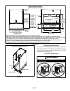
Supply Air Plenum
If the furnace is installed without a cooling coil, a removable
access panel should be installed in the supply air duct. The
access panel should be large enough to permit inspection
of the heat exchanger. The furnace access panel must al
ways be in place when the furnace is operating and it must
not allow leaks.
Return Air Plenum
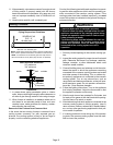
NOTE - Return air must not be drawn from a room
where this furnace, or any other gas-fueled appliance
(i.e., water heater), or carbon monoxide-producing de
vice (i.e., wood fireplace) is installed.
When return air is drawn from a room, a negative pres
sure is created in the room. If a gas appliance is operating
in a room with negative pressure, the flue products can
be pulled back down the vent pipe and into the room. This
reverse flow of the flue gas may result in incomplete com
bustion and the formation of carbon monoxide gas. This
raw gas or toxic fumes might then be distributed through
out the house by the furnace duct system.
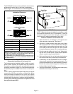
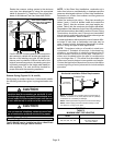
Return air can be brought in through the bottom or either
side of the furnace (return air brought into either side of fur
nace allowed only in upflow applications). If a furnace with
bottom return air is installed on a platform, make an airtight
seal between the bottom of the furnace and the platform to
ensure that the unit operates properly and safely. Use fiber
glass sealing strips, caulking, or equivalent sealing method
between the plenum and the furnace cabinet to ensure a
tight seal. If a filter is installed, size the return air duct to fit
the filter frame.
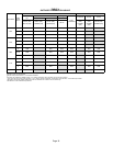
Pipe & Fittings Specifications
All pipe, fittings, primer and solvent cement must conform
with American National Standard Institute and the Ameri
can Society for Testing and Materials (ANSI/ASTM) stan
dards. The solvent shall be free flowing and contain no
lumps, undissolved particles or any foreign matter that ad
versely affects the joint strength or chemical resistance of
the cement. The cement shall show no gelation, stratifica
tion, or separation that cannot be removed by stirring. Re
fer to the table 2 below for approved piping and fitting ma
terials.