


Page 33
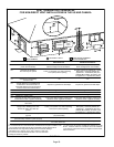
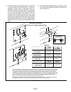
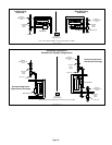
EL296UHE DIRECT VENT APPLICATION
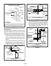
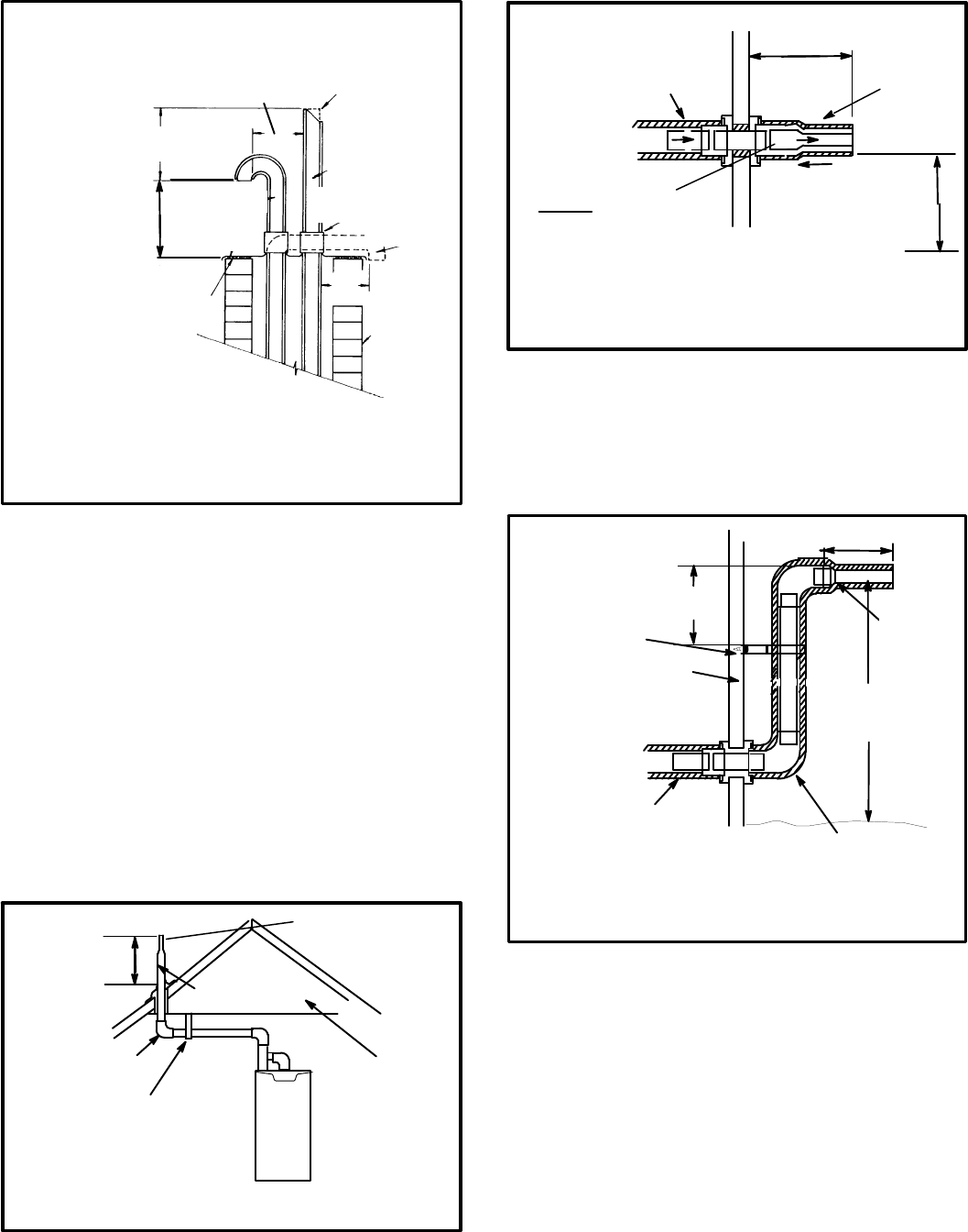
USING EXISTING CHIMNEY
NOTE - Do not discharge exhaust gases directly into any chimney or vent stack. If ver
tical discharge through an existing unused chimney or stack is required, insert piping
inside chimney until the pipe open end is above top of chimney and terminate as illus
trated. In any exterior portion of chimney, the exhaust vent must be insulated.
FIGURE 46
3” - 8”
(76MM-
203MM)
STRAIGHT-CUT OR
ANGLE-CUT IN DIRECTION
OF ROOF SLOPE *
EXHAUST VENT
1/2” (13MM)
WEATHERPROOF
INSULATION
SHOULDER OF FITTINGS
PROVIDE SUPPORT
OF PIPE ON TOP PLATE
ALTERNATE
INTAKE PIPE
INTAKE PIPE
INSULATION (optional)
EXTERIOR
PORTION OF
CHIMNEY
INSULATE
TO FORM
SEAL
SHEET
METAL TOP
PLATE
*SIZE TERMINATION
PIPE PER TABLE 8.
Minimum 12” (305MM)
above chimney top
plate or average snow
accumulation
8” - 12”
(203MM - 305MM)
3”-8”
(76MM-203MM)
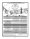
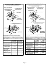
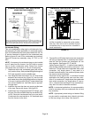
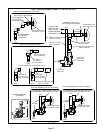
Details of Exhaust Piping Terminations for Non‐Direct
Vent Applications
Exhaust pipes may be routed either horizontally through an
outside wall or vertically through the roof. In attic or closet
installations, vertical termination through the roof is pre
ferred. Figures 47 through 50 show typical terminations.
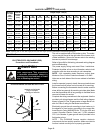
1 - Exhaust piping must terminate straight out or up as
shown. The termination pipe must be sized as listed in
table 8.The specified pipe size ensures proper veloc
ity required to move the exhaust gases away from the
building.
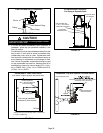
2 - On field supplied terminations for side wall exit, ex
haust piping may extend a maximum of 12 inches
(305MM) for 2” PVC and 20 inches (508MM) for 3”
(76MM) PVC beyond the outside wall. See figure 48.
FIGURE 47
NON-DIRECT VENT ROOF TERMINATION KIT
(15F75 or 44J41)
UNCONDITIONED
ATTIC SPACE
3” (76MM) OR
2” (51MM) PVC
PROVIDE SUPPORT
FOR EXHAUST LINES
12” (305MM)
ABOVE AVE.
SNOW
ACCUMULATION
SIZE TERMINATION
PIPE PER TABLE 8.
1/2” (13MM) FOAM
INSULATION
FIGURE 48
1/2” (13MM) ARMAFLEX
INSULATION IN
UNCONDITIONED SPACE
PVC REDUCER
1/2” (13MM)
ARMAFLEX
INSULATION
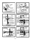
NON-DIRECT VENT FIELD SUPPLIED WALL TERMINATION OR
(15F74) WALL TERMINATION KIT
SIZE TERMINATION
PIPE PER TABLE 8.
FIELD-PROVIDED
REDUCER MAY
BE REQUIRED TO
ADAPT LARGER
VENT PIPE SIZE
TO TERMINATION
12” MIN.
(305MM)
Above Grade or
average snow
accumulation
12” (305MM) MAX. for 2” (51MM)
20” (508MM) MAX. for 3” (76MM)
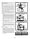
3 - If exhaust piping must be run up a side wall to position
above snow accumulation or other obstructions, pip
ing must be supported every 24 inches (610MM) as
shown in figure 49. When exhaust piping must be run
up an outside wall, any reduction in exhaust pipe size
must be done after the final elbow.
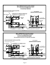
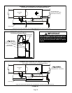
FIGURE 49
12” (305MM)
ABOVE GRADE OR
AVERAGE SNOW
ACCUMULATION
UNCONDITIONED
SPACE
1/2” (13MM) FOAM
INSULATION
1/2” (13MM) FOAM
INSULATION IN
UNCONDITIONED
SPACE
*WALL SUPPORT
OUTSIDE WALL
SIZE TER
MINATION
PIPE PER
TABLE 8.
FIELD-PROVIDED
REDUCER MAY BE
REQUIRED TO
ADAPT LARGER
VENT PIPE SIZE TO
TERMINATION
*Use wall support every 24” (610). Use two supports if extension is
greater than 24” but less than 48”.
12” (305MM) MAX. for 2” (51MM)
20” (508MM) MAX. for 3” (76MM)
NON-DIRECT VENT FIELD SUPPLIED WALL TERMINATION
EXTENDED OR (15F74) WALL TERMINATION VENT PIPE
EXTENDED
6” (152MM)
Max