


Page 40
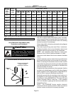
TABLE 10
GAS PIPE CAPACITY - FT
3
/HR (kL/HR)
Nominal
Iron Pipe
Size
inches
(mm)
Internal
Diameter
inches
(mm)
Length of Pipe - feet (m)
10
(3.048)
20
(6.096)
30
(9.144)
40
(12.192)
50
(15.240)
60
(18.288)
70
(21.336)
80
(24.384)
90
(27.432)
100
(30.480)
1/2
(12.7)
.622
(17.799)
172
(4.87)
118
(3.34)
95
(2.69)
81
(2.29)
72
(2.03)
65
(1.84)
60
(1.69)
56
(1.58)
52
(1.47)
50
(1.42)
3/4
(19.05)
.824
(20.930)
360
(10.19)
247
(7.00)
199
(5.63)
170
(4.81)
151
(4.28)
137
(3.87)
126
(3.56)
117
(3.31)
110
(3.11)
104
(2.94)
1
(25.4)
1.049
(26.645)
678
(19.19)
466
(13.19)
374
(10.59)
320
(9.06)
284
(8.04)
257
(7.27)
237
(6.71)
220
(6.23)
207
(5.86)
195
(5.52)
1-1/4
(31.75)
1.380
(35.052)
1350
(38.22)
957
(27.09)
768
(22.25)
657
(18.60)
583
(16.50)
528
(14.95)
486
(13.76)
452
(12.79)
424
(12.00)
400
(11.33)
1-1/2
(38.1)
1.610
(40.894)
2090
(59.18)
1430
(40.49)
1150
(32.56)
985
(27.89)
873
(24.72)
791
(22.39)
728
(20.61)
677
(19.17)
635
(17.98)
600
(17.00)
2
(50.8)
2.067
(52.502)
4020
(113.83)
2760
(78.15)
2220
(62.86)
1900
(53.80)
1680
(47.57)
1520
(43.04)
1400
(39.64)
1300
(36.81)
1220
(34.55)
1160
(32.844)
2-1/2
(63.5)
2.469
(67.713)
6400
(181.22)
4400
(124.59)
3530
(99.95)
3020
(85.51)
2680
(75.88)
2480
(70.22)
2230
(63.14)
2080
(58.89)
1950
(55.22)
1840
(52.10)
3
(76.2)
3.068
(77.927)
11300
(319.98)
7780
(220.30)
6250
(176.98)
5350
(151.49)
4740
(134.22)
4290
(121.47)
3950
(111.85)
3670
(103.92)
3450
(97.69)
3260
(92.31)
NOTE - Capacity given in cubic feet of gas per hour (kilo liters of gas per hour) and based on 0.60 specific gravity gas.
Electrical
ELECTROSTATIC DISCHARGE (ESD)
Precautions and Procedures
CAUTION
Electrostatic discharge can affect elec
tronic components. Take precautions
to neutralize electrostatic charge by
touching your hand and tools to metal
prior to handling the control.
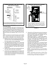
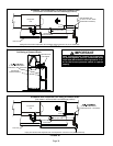
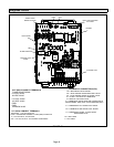
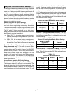
INTERIOR MAKE-UP BOX INSTALLATION
FIGURE 63
MAKE-UP
BOX
Right Side
remove and relocate
plug to unused
opening on left side
The unit is equipped with a field make-up box. The make-
up box may be moved to the right side of the furnace to fa
cilitate installation. Secure the excess wire to the existing
harness to protect it from damage.
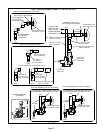
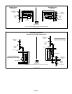
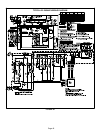
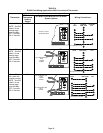
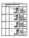
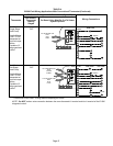
Refer to figure 64 for field wiring, schematic wiring diagram
and troubleshooting.
The power supply wiring must meet Class I restrictions.
Protected by either a fuse or circuit breaker, select circuit
protection and wire size according to unit nameplate.
NOTE - Unit nameplate states maximum current draw.
Maximum Over-Current Protection allowed is 15 AMP.
Holes are on both sides of the furnace cabinet to facilitate
wiring.
Install a separate (properly sized) disconnect switch near
the furnace so that power can be turned off for servicing.
Before connecting the thermostat check to make sure the
wires will be long enough for servicing at a later date. Make
sure that thermostat wire is long enough to facilitate future
removal of blower for service.
Complete the wiring connections to the equipment. Use the
provided unit wiring diagram and the field wiring diagram
shown in figure 64. Use 18-gauge wire or larger that is suit
able for Class II rating for thermostat connections.
Electrically ground the unit according to local codes or, in
the absence of local codes, according to the current Na
tional Electric Code (ANSI/NFPA No. 70) for the USA and
current Canadian Electric Code part 1 (CSA standard
C22.1) for Canada. A green ground wire is provided in the
field make-up box.
NOTE - The EL296UHE furnace contains electronic
components that are polarity sensitive. Make sure that the
furnace is wired correctly and is properly grounded.